www.eaton.
www.eaton.com MX 5000 RT — UPS EXB RT — Extended Battery Transformer 5000 Installation and User Manual Revision History MX Installation and User Manual, 86-87050-00 Revision: A00 ECN#: 004747 04/2006 Revision: A01 ECN#: 004773 05/2006 Copyright © 2008 EATON All rights reserved. For Technical Support, Customer Care Center, or Customer FAQ, please visit our website: www.eaton.
Contents Introduction........................................................................................................................ 5 Important Safety Instructions............................................................................................. 6 Symbol Usage.................................................................................................................... 7 1. Presentation 1.1 1.2 1.3 1.4 1.5 Standard Positions.......................................................
Contents 6. Life Cycle Monitoring (LCM) 6.1 Description....................................................................................................................... 31 7. Maintenance 7.1 Hot Swapping the Power Sub-Module............................................................................. 33 7.2 Hot Swapping the Battery Sub-Module .......................................................................... 33 8. Appendices 8.1 Technical Specifications.......................................
Introduction Thank you for selecting an EATON product to protect your electrical equipment. The MX range has been designed with the utmost care. We recommend that you take the time to read this manual to take full advantage of the many features of your UPS (Uninterruptible Power System). Warning: This is a class A UPS product. In a domestic environment, this product may cause radio interference, in which case, the user may be required to take additional measures.
IMPORTANT SAFETY INSTRUCTIONS SAVE THESE INSTRUCTIONS. This manual contains important instructions that should be followed during installation and maintenance of the UPS and batteries. The MX models that are covered in this manual are intended for installation in an environment within 0° to 40°C, free of conductive contaminant. This equipment has been tested and found to comply with the limits for a Class A digital device, pursuant to Part 15 of the FCC Rules.
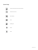
Symbol Usage Important instructions that must always be followed. Information, advice, help. Visual indication. Action. Audible signal. LED off. LED on.
(This page left blank intentionally) 86-87050-00 A02 - Page 8
1. Presentation 1.1 Standard Positions Tower Position Dimensions (H x W x D) in inches/mm MX 5000 RT MX EXB RT Transformer 5000 17.5 x 5.16 x 29.2/ 444.5 x 131 x 741.4 17.5 x 5.16 x 25.6/ 444.5 x 131 x 650 17.5 x 3.5 x 25.6/ 444.5 x 88.9 x 650 Weights in lbs/kg MX 5000 RT 125/57 MX EXB RT 154/70 Transformer 5000 84/38 Rack Position Dimensions (H x W x D) in inches/mm MX 5000 RT MX EXB RT Transformer 5000 5.16 x 17.5 x 29.2/ 131 x 444.5 x 741.4 5.16 x 17.5 x 25.6/ 131 x 444.5 x 650 3.5 x 17.
1. Presentation 1.2 Rear Panels MX 5000 RT MX EXB RT Transformer 5000 14 LOAD 3 BREAKER LOAD 4 BREAKER 1 15 LOAD 3 / 120V~,16A LOAD 4 / 120V~,16A 200-250V~,24A 2 12 3 4 CAUTION: DO NOT DISCONNECT BATTERY CABLE 180VDdc UNDER LOAD BATTERY CONNECTOR 5 11 8 16 9 RS-232 BATT. NO.
1. Presentation 1.3 Display and Control Panel (20) Load protected LED (21) Downgraded operation LED (22) Load not protected LED (23) Alphanumeric display (24) Escape (cancel) button (25) Function buttons (scroll down) (26) Function buttons (scroll up) (27) Enter (confirm) button (28) UPS OFF button (29) UPS ON button (30) Rectifier LED (31) Battery LED (32) Inverter LED (33) Bypass LED (34) Load supplied LED 1.
1. Presentation 1.5 Extended Battery (EXB) MX RT offers a standard backup time of 5 minutes at full load. To increase backup time, it is possible to connect MX EXB RT modules to the UPSs for backup times up to 62 minutes (at full load).
2. Installation 2.1 Unpacking and Contents Check UPS Module Contents (87050) 46 47 option (66102) Optional Transformer Module Contents (87102) 54 51 49 43 45 Step down transformer is designed to provide isolated 120 volts AC outlets.
2. Installation 2.2 Internal Battery Connection (Battery Start-up) 1. Remove the two mounting screws (59) to free the battery disconnect switch (60). 2. Push the battery disconnect switch so that you can read “Connected”. 3. Secure the two mounting screws (59). RS-232 BATT. NO. RPO 59 :T ONEC UTI NN CO T DIS BLE NO Y CA DO TERLOAD BATDER Y R TER TO c UN BATNNEC VDd 180 CO CA A 0V 0-25 ~,24 20 60 Input Cable L6-30P 2.
2. Installation 2.4 Installation in Rack Position Adjustment of the orientation of the logo and control panel 1 2 3 UPS module rack mounting MX RT is very heavy. To ease its rack integration, we strongly recommend to remove the battery tray as shown below. See Section 7.2 for complete instructions on battery removal.
2. Installation Do not install the UPS or battery module in hermetic closed environments without any exchange of air. Follow steps 1 to 4 for rack mounting the UPS onto the rails. The rails and the necessary mounting hardware are supplied by EATON. Note for step 1: It is possible to adjust the position of both front mounting brackets. Rear bracket system (included with rail kits) To be used if you need to move the rack enclosure with UPS already rack-mounted inside.
2. Installation 2.5 Communication Ports MX RT provides 4 communication methods. 1. The RS232 port provides communications using EATON Serial HID UPS transfer (SHUT) protocol. The SHUT protocol is compatible with the power management applications available on the enclosed Solution-Pac 2 CD-Rom. 2. The Output contacts port is used for basic signaling or for protection of IT systems like IBM iSeries (formerly AS400) and more. 3.
2. Installation Remote Power Off communication port (9) Installation of a Remote Power Off function must be carried out in compliance with applicable regulations. In order to fully de-energize MX RT with the RPO port, it is necessary to use a two-position switch (Normally Open or Closed contact). Once switch is energized/de-energized, the UPS shuts off the display and the output of the UPS.
2. Installation Hardwire Connection of Output Power Cable to UPS w This type of connection must be carried out by qualified electrical personnel. w Before carrying out any connection, check that the battery circuit breaker and the upstream protection device (Normal AC source) is open «0» (off). 1. Remove the top of the terminal box cover (2 screws) with the included screwdriver. 2. Insert the output cable/conduit (provided by others) through the cable knockout (2). 3.
2. Installation 2.8 Connection to Output Receptacles RPO 1. Connect the equipment to the UPS 4 NEMA L6-30R. RS-232 BATT. NO. If more than one load is connected to the UPS, the total capacity of the loads should not exceed 30 Amps. :T ONEC UTI NN CO T DIS BLE NO Y CA DO TERLOAD BATDER Y R TER TO c UN BATNNEC VDd 180 CO CA 0V 0-25 20 2.
3. Operation 3.1 Initial Start-Up To ensure that your system is configured in complete accordance with safety regulations and to benefit from the manufacturer’s warranty, please contact Technical Support at www.eaton.com or call (800) 279-7776. 22 1. Check that the battery disconnect switch (60) on top cover is connected (see section 2.2 Internal Battery Connection). 2. Set the upstream circuit breaker (not included) to the on position.
3. Operation 3.3 Operating Modes Normal mode This is the standard operating mode, set by default in the factory. Under normal condition (Normal AC source available): LED (20) is ON. LEDs (30), (32), (34) are green. The equipment is protected by the UPS. ECO mode The main advantage of the Eco mode (see glossary) is that it reduces the consumption of electrical power. Under normal condition (Normal AC source available): LED (20) is ON. LEDs (33), (34) are green. The equipment is supplied in ECO mode.
3. Operation 3.4 Operation on Battery Power When the Normal AC source is not available, the load continues to be protected by the UPS. Power is supplied by the battery. Transfer to battery power LEDs (20), (21) are ON. LEDs (31), (32), (34) are green. The audible alarm beeps every 10 seconds. The equipment is protected by the UPS and supplied by the battery. The display indicates the battery remaining backup time. Low battery warning LEDs (20), (21) are ON. LEDs (31), (32), (34) are green.
3. Operation 3.5 Return to Normal AC Source After an outage, the UPS restarts automatically when Normal AC source is restored (unless this function has been disabled via UPS personalization) and the load is supplied again. 3.6 UPS Shutdown When AC Present Before shutdown, please read ALL instructions below: 22 1. Press and hold the «0” (off) button (28) for 3 seconds. The buzzer beeps once. The load is no longer protected by the UPS. It is powered via the Normal AC source (bypass).
4. Access to Maintenance and Personalization Data 4.1 Display Organization Status and Alarms Measurements UPS input measurements UPS output measurements Battery measurements UPS Set-up Local settings Output settings ON/OFF settings Battery settings Maintenance Model Alarm History Manual battery test Led and Buzzer test LCM Statistics Operation limits 4.2 Access to Measurements Press the scroll button (25)to access measurements for voltage, current, frequency, power output and battery capacity. 4.
4. Access to Maintenance and Personalization Data 4.
4. Access to Maintenance and Personalization Data Battery Personalization Function Factory Setting Options Battery test Every week No test / daily test / monthly Low Batt warning 20% 0 to 100% 1% increment User Battery Settings UPS reads number of battery modules connected From 0 to 40 Ah 5 Ah increment No Protection against deep discharge. If disable, EATON warranty will be void Deep DischargeProtect Yes 4.
(This page left blank intentionally) 86-87050-00 A02 - Page 28
5. Troubleshooting 5.1 Troubleshooting LEDS (21) and (22) If LED (21) is ON: The equipment is protected by the UPS but the operation is downgraded. If LED (22) is ON: The equipment is no longer protected by the UPS. 5.
5. Troubleshooting 5.3 Troubleshooting Requiring EATON After-Sales Support ENVIRONMENT FAULT 27 Displayed Signification Correction POWER MODULE FAULT The battery is incorrectly connected. Internal power sub-module fault detected. Use “Enter” button (27) to display details. See after-sales support at www.eaton.com. Follow the power sub-module replacement procedure (see sections 7.1 and 7.2) BATT MODULE FAULT Battery fault detected during the battery test.
6. Life Cycle Monitoring (LCM) 6.1 Description This function, embedded in the UPS, displays messages on screen, and communication channels, at every important stage of the UPS’s life, allowing you to: Press the “Enter” button (27) to display LCM warning details. Secure your installation power continuity Anticipate needed maintenance actions thanks to automatically displayed warnings: LCM warning details Signification BATTERYCHECK RECOMMENDED CONTACT www.eaton.
(This page left blank intentionally) 86-87050-00 A02 - Page 32
7. Maintenance 7.1 Hot Swapping the Power Sub-Module This operation must be carried out by qualified electrical personnel only. This operation can be performed without interrupting the equipment. Disconnecting the power sub-module (87100): 1. 2. 3. 4. Remove the 6 mounting screws to free the main front panel bezel. Place the front panel above the UPS. Remove the 2 mounting screws on each side of the power sub-module. Withdraw the power sub-module.
86-87050-00 A02 - Page 34
8. Appendices 8.1 Technical specifications MX 5000 5000 VA (1) / 4500 W (2) Output power Electrical supply network w Rated input voltage w Input voltage range w Frequency w Power factor w Leakage current Single phase 208 V 120/156 V to 280 V (3) 50/60 Hz (autoselect) > 0.99 7 mA Load output w Voltage w Frequency w Harmonic distortion w Overload capacity Battery MX EXB Single phase 208 V ±3% (4) 50/60 Hz ±0,5% (5) < 3% 105% continuous, 110% 2min, 125% 1min, > 150% 0.
86-87050-00 A02 - Page 36
8. Appendices EATON Customer Care Center Technical Support and Product Services Technical questions? If you encounter a problem while following the instructions in this manual, or have questions about the operation, repair, or servicing of your equipment, please visit our web site www.eaton.com for complete service information.
86-87050-00 A02 - Page 38
8. Appendices 8.2 Glossary Backup time Time that the connected equipment can operate on battery power. Bypass AC source Source supplying the bypass line. The equipment can be transferred to the bypass line if an overload occurs on the UPS output, for maintenance or in the event of a malfunction. ECO mode Operating mode by which the equipment is supplied directly by the AC source if it is within the tolerances defined by the user. This mode reduces the consumption of electrical power.
Notes 86-87050-00 A02 - Page 40
86-87050-00 A02
www.eaton.