
Installation guide


SMART GRID ENERGY
1
© 2013 Copyright CACHELAN cachelan.com contactus@cachelan.com All rights reserved SolarVu
®
Installation Guide for Eaton PV250 Inverter
SolarVu
®
for Eaton PV250 5kW Inverter
Installation Guide
Site Preparation
SolarVu
®
is an energy portal that enables remote monitoring of renewable
energy generation sites over the web. It requires the installation of a K135
gateway which continuously transfers data from the inverter(s). This guide
explains how to connect the K135 gateway to Eaton PV250 5kW inverters.
Each inverter must have a Super RS485 communications card installed which
is normally a standard feature. To access SolarVu from a browser, the inverters
are connected to the internet through a Cachelan K135 gateway. The K135
connects to multiple inverters using twisted pair wire, typically cat5e, daisy
chained to multiple inverters. An RJ45 ethernet jack, connected to the LAN
network and 120VAC outlet for the gateway power dongle are required. The
LAN must have high speed internet service to an ISP to provide a gateway to
the internet as shown in gure 1.
K135 Installation
Mount the SolarVu enclosure with conduit to the inverter for the 4 wire RS422
serial cable, ethernet cat5e cable and 120VAC control power. Normally this
enclosure will be in the same electrical room as the inverter, however, the RS422
serial cable can run long distances, over 1000 feet, if necessary.
Power Supply: Temporarily unplug the K135 power dongle. Wire 120VAC
control power from a suitable 15A circuit to the the internal receptacle and
replace the cover securing the dongle with the reusable cable tie suppled.
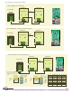
RS422 Serial: Consult the Eaton installation manual and gs 2, 3, 4 for wiring
connections. Cat5e cable can be used (4 pairs) or a cable with 2 twisted pairs (4
wires). Connect to the screw terminals or the RJ45 jacks but not both shown in
g 4. The Rx-, Rx+, Tx-, Tx+ signals on the 2 screw terminal blocks and the RJ45
jacks are connected in parallel. Route twisted pair cable through the inverter
cable entry holes away from power conductors to one set of terminals from the
K135. Then daisy chain to the next inverter using the other terminals being
careful to match signals as shown in g 3. Do not connect in star conguration.
Ensure that both switches on SW2 (left side of 485 board) are in the down
position to enable RS422 communications. If left in the up position (console
programming) the K135 gateway cannot connect to the inverters. For all inverters
except the last one, set both switches on SW1 (right side) to the up position to
disable termination. Only on the last inverter should both SW1 switches be in
the down position to connect the internal 120 ohm termination resistor. This is
optional and only necessary for long wire runs.
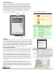
Each inverter requires a unique slave address. Address assignment is done
automatically by the K135 each time the inverter powers up. Unlike most other
other systems, the user does not need to set any communication slave address
for this inverter.
Ethernet: Use a standard ethernet patch cable with RJ45 connectors of the
appropriate length to connect from the K135 to the network ethernet at a RJ45
wall jack or the router/switch.
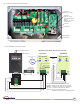
Fig 1 Internet Connection
CABLE/DSL
MODEM
ROOFTOP SOLAR ARRAY
+
DC
K135
GATEWAY
FIREWALL
ROUTER
CORPORATE
ETHERNET
LAN
LOCAL
ACCESS
REMOTE BROWSER
ACCESS
INTERNET
SolarVu
Servers
RS422
ISP
GE788
+
DC
Ethernet
RS422
EATON PV250
INVERTERS
COMBINERS