
Installation Manual


5
Information Booklet IB150001EN
Effective July 2017
Power Xpert
®
Multi-Point Meter
Quick Start Guide
EATON www.eaton.com
Meter Base
Both PXMP Meter Base assembly models are shipped without mod-
ules. The front of the base has a label indicating 10 positions or slots
(1-10), where modules can be mounted. Each position is covered
with a metal slot cover secured to the assembly with screws. The
slot covers protect the backplane of the PXMP-MB assembly. Slot
covers are removed to insert modules, but should be left in place if
the slot is not being used. The ten slots provided are multi-purpose.
They can accommodate any combination of PXMP-MMxxxx (10 mA,
100 mA, or 333 mV), PXMP-PIM, or PXMP-DOM.
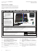
ote:N The PXMP-MB (3-phase 4-Wire Wye, 3-phase 3-Wire Delta (grounded),
and single-phase Metering) can be used on 3-phase, 2-phase, and single-
phase applications. The PXMP-MB-AB (120/240 V, single-phase 3-Wire ser-
vice) can ONLY be used on single-phase applications. The PXMP-MB-AB base
has a yellow label on the lower left of base (see Figures 3 and 4).
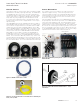
Figure 3. PXMP-MB (White Label).
Figure 4. PXMP-MB-AB (Yellow Label - Shown with Three
Modules Installed).
Meter Base Assembly
The PXMP-MB assembly includes a solid-state relay output that can
be configured as a Pulse Initiator output assigned to any one of the
tenant meters or to the aggregate sum of the tenant meters. An
external 24 Vdc power supply is required to drive the load limited
to 80 mA maximum. The PXMP-MB assembly also includes three
digital status inputs that can be used to indicate conditions such as
a demand synch pulse or a rate alert. These digital inputs require
external 24 Vdc voltage +/- 20% to operate.
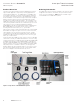
The Mode DIP switches are located behind the metal door cover at
the top left corner of the black label face of the PXMP-MB assembly
panel. These Mode switches are used to secure the PXMP Meter in
one of three levels of hardware enforced security modes. Note the
tab on the base that can be used to seal the door shut for security
purposes.
Figure 5. PXMP-MB Assembly Components and LEDs.
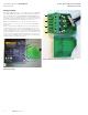
The PXMP-MB assembly includes the following LED indicators:
•
Three LEDs marked A, B, and C, adjacent to the Meter Voltage
Input connector, indicate if voltage is applied to the meter phase
inputs and is within the expected range.
•
Two LED’s are marked Delta or Wye/1PH and used to indicate the
active metering mode configuration.
•
Red and green TX and RX LED’s adjacent to Com 1 and Com 2
provide visual indication of Transmit and Receive activity on the
communication ports.
•
A Health LED indicates that the PXMP-MB main microprocessor
is functioning correctly.
•
A Power LED indicates that 24 Vdc is applied to the 24 Vdc input
to the PXMP-MB.
•
A Status LED indicates that communication activity between the
PXMP-MB and PXMP-MMxxxx.