
Installation Manual


6
Information Booklet IB150001EN
Effective July 2017
Power Xpert
®
Multi-Point Meter
Quick Start Guide
EATON www.eaton.com
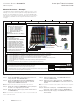
Voltage Inputs
Metering voltage inputs connect to the right side of the PXMP-MB
and PXMP-MB-AB assemblies. Inputs are marked A (V1), B (V2), C
(V3), and N (VR) on both the PXMP-MB and PXMP-MB-AB assem-
blies. If connecting to a Delta system, the unused N (VR) terminal
should be connected to chassis ground. A cover for the voltage ter-
minal is provided as a barrier to hazardous terminal access.
ote:N On the PXMP-MB-AB, even though the voltage input label on the
assembly lists the “C” connection, it will never be used in PXMP-MB-AB
applications.
When commissioning a PXMP Meter, ensure that the phasing is
consistent between the voltage input terminal and the load cur-
rent sensor input connections on the PXMP-MMxxxx. If a current
sensor is plugged into a connection point on the PXMP-MM that is
assigned to a different phase voltage, metering errors will result due
to the current and voltage phasing mismatch (see Sections 4.3.4 -
Current Sensor Installation and 6 - Configuring and Commissioning
of IM150001EN for detailed information).
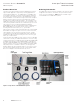
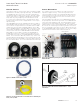
Figure 6. A, B, C, and N Connections on the PXMP-MB Assembly
Meter Voltage Input.
"N" Connections
"C" Connections
"B" Connections
"A" Connections
Figure 7. Meter Voltage Input Terminal Plug and Cover.
N
C
B
A