
Installation Manual


9
Information Booklet IB150001EN
Effective July 2017
Power Xpert
®
Multi-Point Meter
Quick Start Guide
EATON www.eaton.com
Current Sensors
Three different types of current sensors can be used with the PXMP
Meter based on secondary output type and range. The PXMP Meter
is compatible with direct connection to 100 mA, 10 mA, and 333
mV maximum rated secondary current sensors. All single CT appli-
cations require that the CT provides Double/Reinforced Insulation
600V, CATIII. By using interposing current transformers such as
the CS005, current transformers with 1 or 5 Amp outputs can be
interfaced. Each current sensor is slightly different. Some require
special mounting.
The PXMP-MMxxxx are directly compatible with Eaton’s CSXXX 10
mA and PXMP-CSXXX 100 mA current sensors. The CSXXX current
sensors have an integral yellow 4 ft (1.22 m) cable while the PXMP-
CSXXX current sensors require a separate PXMP-SC sensor cable
that is in available 4/6/8/12 ft. (1.22/1.83/2.44/3.66 m) lengths to help
cleanly match the application dimensions. Generic 333 mV output
current sensors must use the PXMP-IM333MV Interface Modules
and a PXMP-SC Sensor Cable to interface with a PXMP-MM. In
a PXMP Meter System, the CSXXX 10 mA secondary output sen-
sors should be connected only to a PXMP-MM10MA 10 mA Meter
Module. The 10 mA sensor cables are yellow in color, ~ 48 in. (1.22
m) long and are built integral with the sensor. Eight and 12 ft. (2.44
and 3.66 m) extensions are available to extend the distance between
the sensor and the Meter. Do not exceed 28 ft (8.53 m) total length.
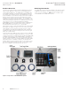
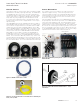
Figure 13. PXMP-CSXXX Current Sensor - 100 mA.
Figure 14. PXMP Current Sensor Cable.
Figure 15. 10 mA CS125 Solid Core Current Sensor with Integral
48 in. (1.22 m) Cable.
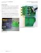
Sensor Orientation
The orientation of the sensor relative to the load current flow is
important for proper metering. Current sensing is directional.
Sensors should be mounted on the insulated load cables facing the
load current back to front as shown by the arrow on top of the sen-
sor or similar direction marking. An incorrect orientation results in
an incorrect energy reading.
Two LED indicators per load circuit on the PXMP-MM will indicate
the power polarity. Note that the green LED on the PXMP-MM indi-
cates current flow towards the load. The red LED indicates current
is flowing from the load towards the source. Normally, a red LED
indicates that the sensor is mounted backwards. The red LED would
be correct if the circuit being monitored is a generator not a load. If
there is not adequate current flow, the sensor cable is disconnected
or the PXMP-MB assembly is powered down, or if the meter voltage
inputs are disconnected then these indicators will be off.
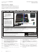
Figure 16. Typical Wiring Arrangement of Sensor Connected to
Meter Module.
Figure 17. CS050/125/200/400 Current Sensors – Load
Orientation.
Breaker
Sensors
Sensor
Cables
Meter Modules
To Sourcing Breaker
Yellow Secondary Cable