
Specification


3
EATON www.eaton.com/wiringdevices
Technical Data
Effective September 2017
Z-Wave wireless smart
master dimmer
Project Name: Prepared By:
Project Number: Date:
Catalog Number: Type:
Parameter Description Value range
1 Delayed OFF time *0 to 127
-128 to -1
2 Panic ON time *0 to 127
-128 to -1
3 Panic OFF time *0 to 127
-128 to -1
4 Basic set value *0 to 127
-128 to -1
5 Power up state 1=OFF, 2=ON, 3=Last state
6 Panic mode enable 0=OFF, 1=ON
7 Dimmer ramp time *0 to 127
-128 to -1
8 Kickstart enable/disable 0 disables, 1 enables
9 Reset max/min levels to factory default 0
11 Set minimum dimming level *** 4 to 99
12 Set maximum dimming level *** 4 to 99
*The configuration value is a signed single byte number. This value may represent a value with no units or may represent a value such as time. 0 to 127 (decimal) represents 0 to 127
seconds of time. -128 to -1 (negative decimal numbers) represents 128 to 255 seconds as calculated by this formula.
Config value = desired time in seconds (or desired value) -256
For an example of 172 seconds: config value = 172 - 256 = -84 (decimal) or 0xAC (hex)
**Normally this parameter will not be changed and should be left at factory default unless specific associated devices require a fixed value. It is included to ensure Z-Wave
®
certification requirements. If a value other than 0 is configured, then the device will send the configured value rather than the actual value of the dim level to associated devices.
Changing this value from 0 will result in undesired operation in most cases.
***Please note that these values are not normally used except for possible technical support troubleshooting in the case of attempting to set the dimming level to determine
solutions to lamp incompatibility issues.The minimum level must always be at least 13 below the maximum level.
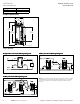
The customer may change this level by following the instructions in the intruction sheet for the product. These instructions tell the customer to press and hold the ON/OFF button
for a specified period of time, observe the LEDs, and take certain actions to be able to make these adjustments.
Table 5. Device Configuration Parameters
Association Groups for RF9540-N
Group 1 5 nodes maximum
Group 2 - 254 0 nodes maximum
Group 255 1 node maximum
Table 6. Device Association Information
Compliances, specifications and availability are subject to change without notice.