Instruction Manual IM01005019E - Rev.
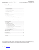
Instruction Manual IM01005019E - Rev. 5 Effective November 2013 Eaton SPD Series Surge Protective Device for Integrated Units Table of Contents 1.0 Introduction ....................................................................................... 1 1.1 Manual Organization ...................................................................1 1.2 Product Overview ....................................................................... 1 1.3 Safety Precautions ...............................................
Eaton SPD Series Surge Protective Device for Integrated Units Instruction Manual IM01005019E - Rev.5 Effective November 2013 1.0 Introduction WARNING 1.1 Manual Organization This Installation Manual describes the safe installation, testing and operation of the Eaton® SPD Series Surge Protective Device (SPD). This manual is organized into seven sections, as follows: 1.0 Introduction 2.0 Installation 3.0 Operating Features 4.0 Troubleshooting 5.
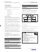
Eaton SPD Series Instruction Manual IM01005019E - Rev. 5 Surge Protective Device for Integrated Units Effective November 2013 NOTICE 1.5 Equipment Testing WARNING CONDUCTING DIELECTRIC, MEGGER, OR HI-POTENTIAL TESTING WITH THE SPD INSTALLED WILL CAUSE INTERNAL DAMAGE TO THE SPD. THE SPD WILL ALSO CAUSE THE TEST TO FAIL. Every Eaton SPD Series unit is tested at the factory for dielectric breakdown. No further SPD testing is required for installation.
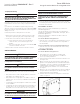
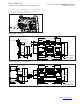
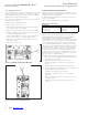
Eaton SPD Series Instruction Manual IM01005019E - Rev.5 Surge Protective Device for Integrated Units Effective November 2013 6. Select the correct wiring diagram for the SPD you are installing. You must refer to this diagram while wiring the SPD. See Figures 6, 7, 8, and 9, on page 4. Figure 3. Bus Connection MOUNTING 8.80 [223.5] 4X MTG .19 [4.8] BUS .34 [8.5] .04 [1.0] 4.40 [111.8] 2.015 [51.2] 3X Ø.221 BUS MTG 2.015 [51.2] .95 [24.0] 5.40 [137.0] MTG 3.42 [86.9] 4.66 [118.4] 3.42 [86.
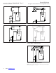
Instruction Manual IM01005019E - Rev. 5 Effective November 2013 Eaton SPD Series Surge Protective Device for Integrated Units Figure 6. Wiring - Single Phase Units (230 L) Figure 8. Wiring - 3-Phase Delta Units Figure 7. Wiring - Split Phase Units Figure 9. Wiring - 3-Phase Wye Units Figure 10. Wiring - High Leg Delta Units NNote: Please consult the factory for 240 delta high leg (4W+G) applications with high leg on the 'C' Phase. 4 Eaton www.eaton.
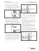
Eaton SPD Series Surge Protective Device for Integrated Units Instruction Manual IM01005019E - Rev.5 Effective November 2013 7. Connect the System Ground wire (green) to the SPD’s Surge Ground connection using a ring terminal suitable for use with a #10 fastener and a #10-32 x 3/8" fastener (customer supplied). Tighten the Surge Ground connection to 4.1 Nm (36 in-lbs). If the system uses an isolated ground, connect the isolated ground wire to Surge Ground.
Instruction Manual IM01005019E - Rev. 5 Effective November 2013 6. Connect the System Ground wire (green) to the SPD’s Surge Ground connection using a ring terminal suitable for use with a #10 fastener and #10-32 x 3/8" fastener (customer supplied). Tighten the Surge Ground connecion to 4.1 Nm (36 in-lbs). If the system uses an isolated ground, connect the isolated ground wire to Surge Ground. There are two Surge Ground connection points provided on the SPD. Connect only one of them. See Figure 11. 7.
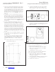
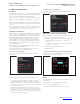
Eaton SPD Series Instruction Manual IM01005019E - Rev.5 Surge Protective Device for Integrated Units Effective November 2013 3.0 Operating Features 3.2.2 Standard Feature Package 3.1 General The Eaton SPD Series Standard Feature Package display is shown in Figure 19. The Eaton SPD Series comes in three feature packages: Basic, Standard, and Standard with Surge Counter. The operating specifics of each feature package are described below.
Instruction Manual IM01005019E - Rev. 5 Effective November 2013 Eaton SPD Series Surge Protective Device for Integrated Units 3.2.4 SPD Display Rotation 3.3 Remote Display Panel (RDP) Option The SPD display can be rotated on the SPD enclosure, up to 360 degrees. This allows you to position the display for the best visibility regardless of the position in which the SPD is installed. The Eaton Series SPD displays may be monitored on a remote display panel (RDP).
Eaton SPD Series Surge Protective Device for Integrated Units Instruction Manual IM01005019E - Rev.5 Effective November 2013 4.0 Troubleshooting Many SPD failures result from improper installation. Once the SPD is installed properly, it is a highly reliable unit. If the SPD does not function properly, first confirm that it is installed properly. See Section 2, “Installation.” If the SPD malfunctions after it has been operating routinely, refer to Table 3.
Instruction Manual IM01005019E - Rev. 5 Effective November 2013 Eaton SPD Series Surge Protective Device for Integrated Units 5.0 Specifications Table 4.
Eaton SPD Series Instruction Manual IM01005019E - Rev.5 Surge Protective Device for Integrated Units Effective November 2013 6.0 Ordering Guidelines Table 5.
Instruction Manual IM01005019E - Rev. 5 Effective November 2013 7.0 Warranty Eaton warrants these products for a period of 10 years from the date of delivery to the purchaser , 15 years if the product is properly registered with Eaton, to be free from defects in both workmanship and materials.