Powerware Series ® Eaton 9395 Maintenance Bypass Module 275 kVA and 550 kVA Installation and Operation Manual
Powerware Series ® Eaton 9395 Maintenance Bypass Module 275 kVA and 550 kVA Installation and Operation Manual
IMPORTANT SAFETY INSTRUCTIONS SAVE THESE INSTRUCTIONS This manual contains important instructions that you should follow during installation and maintenance of the UPS and batteries. Please read all instructions before operating the equipment and save this manual for future reference.
Table of Contents 1 Introduction . . . . . . . . . . . . . . . . . . . . . . . . . . . . . . . . . . . . . . . . . . . . . . . . . . . . . . . . . . . . . . . . . . . . . . . . . . . 1.1 2 1-1 MBM Standard Features . . . . . . . . . . . . . . . . . . . . . . . . . . . . . . . . . . . . . . . . . . . . . . . . . . . . . . . . . . . . . . . . . . . . . . . . . . . . . . . . 1.1.1 Installation Features . . . . . . . . . . . . . . . . . . . . . . . . . . . . . . . . . . . . . . . . . . . . . . . . . . . .
TABLE OF CONTENTS Section II – Operation 5 Understanding MBM Operation . . . . . . . . . . . . . . . . . . . . . . . . . . . . . . . . . . . . . . . . . . . . . . . . . . . . . . . . . . . 5.1 5.2 5.3 5.4 5.5 6 MBM with Electrical Interlocks . . . . . . . . . . . . . . . . . . . . . . . . . . . . . . . . . . . . . . . . . . . . . . . . . . . . . . . . . . . . . . . . . . . . . . . . . . . . MBM with Mechanical (Kirk Key) Interlocks . . . . . . . . . . . . . . . . . . . . . . . . . . . . . . . . . . . .
TABLE OF CONTENTS List of Figures Figure 1‐1. Eaton 9395 MBM . . . . . . . . . . . . . . . . . . . . . . . . . . . . . . . . . . . . . . . . . . . . . . . . . . . . . . . . . . . . . . . . . . . . . . . . . . . Figure 3‐1. MBM Cabinet Dimensions (Front View) . . . . . . . . . . . . . . . . . . . . . . . . . . . . . . . . . . . . . . . . . . . . . . . . . . . . . . . . . . . . Figure 3‐2. MBM Cabinet Dimensions (Right Side View) . . . . . . . . . . . . . . . . . . . . . . . . . . . . . . . . . . . . . . .
TABLE OF CONTENTS This page intentionally left blank. iv Eaton 9395 Maintenance Bypass Module Installation and Operation Manual S 164201719 Rev 3 www.eaton.
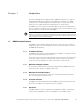
Chapter 1 Introduction Figure The Eaton® 9395 Maintenance Bypass Module (MBM) is designed for use with the Eaton 9395 225–550 kVA three-phase uninterruptible power supplies. The MBM enables power to completely bypass and isolate the UPS so that the UPS can be safely serviced or replaced without interrupting power to critical systems. The MBM is housed in a single, free‐standing cabinet with safety shields behind the doors for hazardous voltage protection.
INTRODUCTION Figure 1‐1. Eaton 9395 MBM 1.2 Options and Accessories Contact an Eaton sales representative for information about the following options. 1.2.1 Bypass Input Breaker An optional bypass input breaker (BIB) provides a single point of input power control to the UPS and easily removes power from the UPS for servicing. 1.2.
INTRODUCTION 1.3 Basic System Configurations The following basic MBM configurations are possible: S MBM with MBP and MIS S MBM with MBP, MIS, and BIB S MBM with MBP, MIS, BIB, and RIB 1.4 Using This Manual This manual describes how to install and operate the Eaton 9395 MBM. Read and understand the procedures described in this manual to ensure trouble-free installation and operation. The information in this manual is divided into sections and chapters.
INTRODUCTION 1.6 Symbols, Controls, and Indicators The following are examples of symbols used on the MBM or accessories to alert you to important information: RISK OF ELECTRIC SHOCK - Observe the warning associated with the risk of electric shock symbol. CAUTION: REFER TO OPERATOR'S MANUAL - Refer to your operator's manual for additional information, such as important operating and maintenance instructions.
INTRODUCTION 1.8 Getting Help If help is needed with any of the following: S Scheduling initial startup S Regional locations and telephone numbers S A question about any of the information in this manual S A question this manual does not answer Please call the Help Desk at: United States: Canada: All other countries: 1-800-843-9433 or 1-919-870-3028 1-800-461-9166 ext 260 Call your local service representative Eaton 9395 Maintenance Bypass Module Installation and Operation Manual S 164201719 Rev 3 www.
INTRODUCTION This page intentionally left blank. 1-6 Eaton 9395 Maintenance Bypass Module Installation and Operation Manual S 164201719 Rev 3 www.eaton.
Chapter 2 Figure Safety Warnings IMPORTANT SAFETY INSTRUCTIONS SAVE THESE INSTRUCTIONS This manual contains important instructions that should be followed during installation and maintenance of the MBM. Read all instructions before operating the equipment and save this manual for future reference. The MBM cabinet is designed for industrial or computer room applications, and contains safety shields behind the doors.
SAFETY WARNINGS This page intentionally left blank. 2-2 Eaton 9395 Maintenance Bypass Module Installation and Operation Manual S 164201719 Rev 3 www.eaton.
Section I Installation Eaton 9395 Maintenance Bypass Module Installation and Operation Manual S 164201719 Rev 3 www.eaton.
2-2 Eaton 9395 Maintenance Bypass Module Installation and Operation Manual S 164201719 Rev 3 www.eaton.
Chapter 3 MBM Installation Plan and Unpacking Figure Use the following basic sequence of steps to install the Maintenance Bypass Module (MBM): 1. Create an installation plan for the MBM (Chapter 3). 2. Prepare your site for the MBM (Chapter 3). 3. Inspect and unpack the MBM cabinet (Chapter 3). 4. Unload and install the MBM cabinet, and wire the system (Chapter 4). 5. Complete the Installation Checklist (Chapter 4). 6.
MBM INSTALLATION PLAN AND UNPACKING The UPS equipment operating environment must meet the weight requirements shown in Table 3‐1 and the size requirements shown in Figure 3‐1 through Figure 3‐4. Dimensions are in millimeters (inches). Table 3‐1.
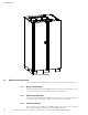
MBM INSTALLATION PLAN AND UNPACKING Dimensions are in millimeters [inches]. Figure 3‐1. MBM Cabinet Dimensions (Front View) Dimensions are in millimeters [inches]. Figure 3‐2. MBM Cabinet Dimensions (Right Side View) Eaton 9395 Maintenance Bypass Module Installation and Operation Manual S 164201719 Rev 3 www.eaton.
MBM INSTALLATION PLAN AND UNPACKING Front Dimensions are in millimeters [inches]. Figure 3‐3. MBM Cabinet Dimensions (Top View) Front Dimensions are in millimeters [inches]. Figure 3‐4. MBM Cabinet Dimensions (Bottom View) 3-4 Eaton 9395 Maintenance Bypass Module Installation and Operation Manual S 164201719 Rev 3 www.eaton.
MBM INSTALLATION PLAN AND UNPACKING 3.2.2 MBM Power Wiring Preparation Read and understand the following notes while planning and performing the installation: S Refer to national and local electrical codes for acceptable external wiring practices. S For external wiring, use 90°C copper wire. If wire is run in an ambient temperature greater than 30°C, higher temperature wire and/or larger size wire may be necessary. Wire sizes are based on using the specified breakers.
MBM INSTALLATION PLAN AND UNPACKING For external wiring requirements, including the minimum AWG size of external wiring, see Table 3‐4 and Table 3‐5 for the 9395 275 kVA MBM or Table 3‐6 and Table 3‐7 for the 9395 550 kVA MBM. Table 3‐4.
MBM INSTALLATION PLAN AND UNPACKING Table 3‐5.
MBM INSTALLATION PLAN AND UNPACKING Table 3‐6.
MBM INSTALLATION PLAN AND UNPACKING Table 3‐7.
MBM INSTALLATION PLAN AND UNPACKING The power wiring terminals are compression lugs, UL and CSA rated at 90°C. See Table 3‐8 and Table 3‐9 for power cable terminations. Figure 4‐9 on page 4-11 and Figure 4‐10 on page 4-12 show the location of the power cable terminals inside the MBM. Table 3‐8. Power Cable Terminations for the Eaton 9395 275 kVA MBM Terminal Function Size of Pressure Termination Tightening Torque Nm (lb in) Hex Size E1 Phase A 2 - #6-350 kcmil 31.
MBM INSTALLATION PLAN AND UNPACKING Table 3‐9. Power Cable Terminations for the Eaton 9395 550 kVA MBM Terminal Function Size of Pressure Termination Tightening Torque Nm (lb in) Hex Size E1 Phase A 4 - #2-600 kcmil 56.5 (500) 1/2” Hex E2 Phase B 4 - #2-600 kcmil 56.5 (500) 1/2” Hex E3 Phase C 4 - #2-600 kcmil 56.5 (500) 1/2” Hex RIB-1 Phase A 4 - 3/0-400 kcmil 31.1 (275) 5/16” Hex RIB-3 Phase B 4 - 3/0-400 kcmil 31.1 (275) 5/16” Hex RIB-5 Phase C 4 - 3/0-400 kcmil 31.
MBM INSTALLATION PLAN AND UNPACKING External MBM rectifier and bypass input overcurrent protection is not provided by this product, but is required by codes. Refer to Table 3‐4 through Table 3‐7 on pages 3-6 through 3-9 for wiring requirements. Table 3‐10 lists the recommended maximum rating for rectifier input circuit breakers and Table 3‐11 lists the maximum recommended rating for bypass input circuit breakers. Table 3‐10.
MBM INSTALLATION PLAN AND UNPACKING 3.2.3 MBM Interface Wiring Preparation Control wiring for features and options should be connected at the customer interface terminal blocks located inside the MBM. WARNING Do not directly connect relay contacts to the mains related circuits. Reinforced insulation to the mains is required. Read and understand the following notes while planning and performing the installation: S Use Class 1 wiring methods (as defined by the NEC) for interface wiring up to 30V.
MBM INSTALLATION PLAN AND UNPACKING NOTE The MBM cabinet is shipped with a debris shield covering the ventilation grill on top of the unit. Do not remove the debris shield until installation is complete. 4. Remove the protective covering from the cabinet. 5. Remove the packing material, and discard or recycle in a responsible manner. 6. Inspect the contents for any evidence of physical damage, and compare each item with the Bill of Lading.
Chapter 4 4.1 Figure MBM Installation Preliminary Installation Information WARNING Installation should be performed only by qualified personnel. Refer to the following while installing the Maintenance Bypass Module (MBM): S Chapter 3 for cabinet dimensions, equipment weight, wiring and terminal data, and installation notes. S Do not tilt the cabinet more than "10° during installation. S Remove the conduit landing plates to add conduit landing holes as required. Plate material is 16 gauge steel (1.
MBM INSTALLATION 5. Pull the pallet from under the MBM cabinet. Discard or recycle the pallet and unused shipping brackets in a responsible manner. 6. Carefully lower the MBM cabinet until the cabinet base contacts the floor. 7. Proceed to paragraph 4.3. Front Doors Shipping Bracket Bolts Pallet Shipping Bracket Bolts Left Side Shipping Bracket Figure 4‐1. Removing the Left Side Shipping Bracket 4-2 Eaton 9395 Maintenance Bypass Module Installation and Operation Manual S 164201719 Rev 3 www.
MBM INSTALLATION Front Doors Shipping Bracket Bolts Pallet Right Side Shipping Bracket Shipping Bracket Bolts Figure 4‐2. Removing the Right Side Shipping Bracket 4.3 MBM Installation The method used to install the MBM depends on the type of installation. The MBM can be installed as a line-up-and-match or standalone system. The term line-up-and-match refers to cabinets that are physically attached to the UPS, and the wiring between them is internal.
MBM INSTALLATION 4.3.1 Line-up-and-Match Cabinet Installation Use this procedure to install the MBM adjacent to the Eaton 9395 UPS cabinet (see Figure 4‐3 or Figure 4‐4). The MBM must be located to the left side of the UPS. 1. Verify that the UPS is properly installed and secured. Refer to the applicable Eaton 9395 Installation and Operation manual listed in paragraph 1.7 on page 1-4 for installation instructions. 2.
MBM INSTALLATION Figure 4‐3. Line-up-and-Match MBM with a Eaton 9395 225–275 kVA UPS Figure 4‐4. Line-up-and-Match MBM with a Eaton 9395 450–550 kVA UPS Eaton 9395 Maintenance Bypass Module Installation and Operation Manual S 164201719 Rev 3 www.eaton.
MBM INSTALLATION UPS Front Wire Entry Plate and Wiring Access Figure 4‐5. UPS Left Side View Wiring Access to route wires between cabinets. Figure 4‐6. MBM Cabinet Right Side View 4-6 Eaton 9395 Maintenance Bypass Module Installation and Operation Manual S 164201719 Rev 3 www.eaton.
MBM INSTALLATION Screw from Kit Screw from Kit Screw from Kit Screw from Kit Back Bracket from Kit MBM Top UPS Top Bracket from Kit MBM Top UPS Top Front Top View Rear Bracket Top View Front Bracket Bracket from Kit UPS Base MBM Base Front View Base Bracket Screw from Kit Screw from Kit Figure 4‐7. MBM to Eaton 9395 UPS Joining Brackets 4.3.2 Line-up-and-Match Power Wiring Installation NOTE The MBM cabinet is shipped with a debris shield covering the ventilation grill on top of the unit.
MBM INSTALLATION 3. If not already removed, remove the doors. Remove the retaining screws located inside each door at the top and bottom hinge pivot points, then lift the door off. Retain the hardware for later use. 4. If not already removed, remove the screws securing the top and bottom internal safety shield panels and remove the panels to gain access to the MBM terminals. Retain the hardware for later use. 5.
MBM INSTALLATION 12. If wiring an MBM with a bypass input breaker (BIB), or BIB and rectifier input breaker (RIB), proceed to Step 13; otherwise, proceed to Step 18. 13. An MBM-to-UPS bypass input wiring harness is supplied inside the MBM. Route the harness through the wiring access in the side of the cabinets (see Figure 4‐5 and Figure 4‐6) to the UPS bypass input terminals. Refer to the applicable Eaton 9395 Installation and Operation manual listed in paragraph 1.
MBM INSTALLATION Ventilation Grill Debris Shield (Remove shield before operating system.) Top Entry Conduit Landing for AC Input, AC Output, and Interface Connections (Remove panel to drill or punch conduit holes.) TOP VIEW Front Front Bottom Entry Conduit Landing for AC Input, AC Output, and Interface Connections (Remove panel to drill or punch conduit holes.) BOTTOM VIEW Figure 4‐8.
MBM INSTALLATION AC Input from UPS to MIS (A, B, C) (See Figure 4‐10 for details.) AC Output to Critical Load (A, B, C) (See Figure 4‐10 for details.) Neutral (E12) Terminals (See Figure 4‐10 for details.) AC Output from Optional BIB to UPS (A, B, C) (See Figure 4‐10 for details.) AC Input to Maintenance Bypass (A, B, C) (See Figure 4‐10 for details.) Ground Terminals (See Figure 4‐10 for details.) AC Output from Optional RIB to UPS (A, B, C) (See Figure 4‐10 for details.) Figure 4‐9.
MBM INSTALLATION ` Phase A (E13) Phase A (MIS-1) AC Input from UPS to MIS Phase B (MIS-3) Phase C (MIS-5) Phase B (E14) AC Output to Critical Load Phase C (E15) Neutral Terminals (E12) AC Output from Optional BIB to UPS Phase A (BIB-1) Phase B (BIB-3) Phase C (BIB-5) Phase A (E1) AC Output from Optional RIB to UPS Phase A (RIB-1) Phase B (E2) AC Input to Maintenance Bypass Phase B (RIB-3) Phase C (RIB-5) Phase C (E3) Ground Terminals Figure 4‐10.
MBM INSTALLATION AC Input from UPS to MIS (A, B, C) (See Figure 4‐12 for details.) AC Output to Critical Load (A, B, C) (See Figure 4‐12 for details.) Neutral (E12) Terminals (See Figure 4‐12 for details.) AC Output from Optional BIB to UPS (A, B, C) (See Figure 4‐12 for details.) AC Input to Maintenance Bypass (A, B, C) (See Figure 4‐12 for details.) Ground Terminals (See Figure 4‐12 for details.) AC Output from Optional RIB to UPS (A, B, C) (See Figure 4‐12 for details.) Figure 4‐11.
MBM INSTALLATION ` Phase A (E13) Phase A (MIS-1) AC Input from UPS to MIS Phase B (MIS-3) Phase C (MIS-5) Phase A (BIB-1) AC Output from Optional BIB to UPS Phase B (E14) AC Output to Critical Load Phase C (E15) Neutral Terminals (E12) Phase B (BIB-3) Phase C (BIB-5) Phase A (E1) Phase A (RIB-1) AC Output from Optional RIB to UPS Phase B (E2) AC Input to Maintenance Bypass Phase B (RIB-3) Phase C (E3) Phase C (RIB-5) Ground Terminals Figure 4‐12.
MBM INSTALLATION 4.3.3 Line-up-and-Match TB1 Interface Wiring Installation WARNING Hazardous voltages are present near the user interface terminal area if the MBM is not totally disconnected. NOTE If wiring between the UPS and MBM interface terminals can not be routed through the line-up-and-match cabinets, conduit must be installed between the UPS and MBM cabinets for the wiring. See paragraph 4.3.6 for standalone interface wiring installation instructions.
MBM INSTALLATION Table 4‐1.
MBM INSTALLATION TB1 TB2 (optional) (See Figure 4‐14 for detail.) Figure 4‐13. Interface Terminal Locations 1 MBP Aux #2 NC MBP Aux #2 Common MBP Aux #2 NO MIS Aux #2 NC 10 MIS Aux #2 Common MIS Aux #2 NO Not Used Not Used K3 NC Aux K3 Aux Common MBM TB1 1 TB2 10 RIB Aux #2 NC RIB Aux #2 Common RIB Aux #2 NO BIB Aux #2 NC BIB Aux #2 Common BIB Aux #2 NO Figure 4‐14.
MBM INSTALLATION Maintenance Bypass Monitoring Terminations From To Description UPS TB1-9 (Output Contactor K3 NC Aux) MBM TB1-9 (Output Contactor K3 NC Aux) UPS TB1-10 (Output Contactor K3 Aux Common) MBM TB1-10 (Output Contactor K3 Aux Common) UPS TB3-9 (Building Alarm 5) MBM TB1-3 (MBP Aux #2 NO) UPS TB3-10 (Building Alarm 5 Return) MBM TB1-2 (MBP Aux #2 Common) UPS on bypass UPS on maintenance bypass (Program UPS building alarm for UPS on Maintenance Bypass.
MBM INSTALLATION 4.3.4 Standalone Cabinet Installation To install an MBM located separately from the Eaton 9395 UPS cabinet (see Figure 4‐16 and Figure 4‐17): 1. Verify that the UPS is properly installed and secured. Refer to the applicable Eaton 9395 Installation and Operation manual listed in paragraph 1.7 on page 1-4 for installation instructions. 2. Using a forklift, move the MBM cabinet to the final installed location. 3. Carefully lower the MBM cabinet until the cabinet base contacts the floor.
MBM INSTALLATION Figure 4‐16. Standalone MBM with an Eaton 9395 225–275 kVA UPS Figure 4‐17. Standalone MBM with an Eaton 9395 450–550 kVA UPS 4-20 Eaton 9395 Maintenance Bypass Module Installation and Operation Manual S 164201719 Rev 3 www.eaton.
MBM INSTALLATION 4.3.5 Standalone Power Wiring Installation NOTE The MBM cabinet is shipped with a debris shield covering the ventilation grill on top of the unit. Do not remove the debris shield until installation is complete. However, remove the shield before using the MBM. Once the debris shield is removed, do not place objects on the ventilation grill. NOTE All power wiring to the MBM must be run in customer-supplied conduit.
MBM INSTALLATION NOTE When installing an MBM, a minimum of two separate feeds with upstream feeder breakers, or a single feed with two upstream feeder breakers, must be provided: one for the UPS or rectifier input breaker (RIB) (if installed) and one for the maintenance bypass input. DO NOT use a single feed or a single feeder breaker to supply both the UPS or RIB and the maintenance bypass.
MBM INSTALLATION 20. When all wiring is complete, reinstall the safety shield panels removed in previous steps. 21. Reinstall the doors removed in previous steps and secure with the retained hardware. 22. Close the doors and secure the latch. 4.3.6 Standalone TB1 Interface Wiring Installation WARNING Hazardous voltages are present near the user interface terminal area if the MBM is not totally disconnected.
MBM INSTALLATION 4.3.7 MBP, MIS, BIB, and RIB Current Settings The MBP, MIS, BIB, and RIB are adjustable trip breakers set at the factory. These breakers are designed to control the input and output to the UPS. Verify the settings of the installed MBP, MIS, BIB, and RIB match the values listed in Table 4‐2 and Table 4‐3. Use the continuous current (Ir) dial on each breaker to adjust the trip current as necessary. Table 4‐2.
MBM INSTALLATION 4.5 Completing the Installation Checklist The final step in installing the MBM is completing the following Installation Checklist. This checklist ensures that you have completely installed all hardware, cables, and other equipment. Complete all items listed on the checklist to ensure a smooth installation. Make a copy of the Installation Checklist before filling it out, and retain the original.
MBM INSTALLATION Notes _________________________________________________________________________ _________________________________________________________________________ _________________________________________________________________________ _________________________________________________________________________ _________________________________________________________________________ _________________________________________________________________________ ____________________________________________
Section II Operation Eaton 9395 Maintenance Bypass Module Installation and Operation Manual S 164201719 Rev 3 www.eaton.
4-28 Eaton 9395 Maintenance Bypass Module Installation and Operation Manual S 164201719 Rev 3 www.eaton.
Chapter 5 Figure Understanding MBM Operation The Maintenance Bypass Module (MBM) enables power to completely bypass and isolate the UPS so that the UPS can be safely serviced or replaced without interrupting power to critical systems. The MBM consists of a maintenance bypass breaker (MBP), a maintenance isolation breaker (MIS), an optional bypass input breaker (BIB), and an optional rectifier input breaker (RIB).
UNDERSTANDING MBM OPERATION Key A is removed from the the solenoid lock, inserted in the MBP key A slot, and the MBP closed. This sequence inhibits the MBP from being closed until the UPS is in Bypass mode, preventing the bypass source and the UPS inverter from being connected in parallel. Key B is removed from the MBP, inserted into the key B slot on the MIS, and the MIS opened. When the MIS is locked using key B, key A from the MIS to be removed and inserted into the solenoid lock and locked in place.
UNDERSTANDING MBM OPERATION 5.4 Maintenance Bypass Mode Current Flow An MBP is used to safely supply utility power to the critical load during periods of UPS maintenance or repairs. The bypass source supplies the commercial AC power to the load directly. When the MBP is closed, the load is wrapped around the UPS while power is still supplied to the load by the UPS through the MIS. The MIS is then opened, isolating the UPS from the bypass power source.
UNDERSTANDING MBM OPERATION 5.5 MBM Oneline Configurations The MBM oneline drawings in this section show the simplified internal structure of the maintenance bypass.
UNDERSTANDING MBM OPERATION AC Input to UPS Rectifier 3 Wire A-B-C Rotation AC Input to Bypass 3 or 4 Wire A-B-C Rotation AC Input to Maintenance Bypass 3 or 4 Wire A-B-C Rotation A E1, E2, E3 Single-Feed Kit E6, E7, E8, E12 E1, E2, E3, E12 (Not supplied with the UPS) Input Breaker (CB1) (optional) Input Contactor (K1) Fuse Maintenance Bypass Breaker (MBP) Backfeed Contactor (K5) Rectifier Fuse Static Switch Fuse Fuse Battery Breaker Inverter Output Contactor (K3) D E9, E10, E11, E12 Batte
UNDERSTANDING MBM OPERATION AC Input to Maintenance Bypass 3 or 4 Wire A-B-C Rotation AC Input to UPS Rectifier 3 Wire A-B-C Rotation A E1, E2, E3 E1, E2, E3, E12 C BIB-1, BIB-2, BIB-3, E12 E6, E7, E8, E12 Bypass Input Breaker (BIB) Input Breaker (CB1) (optional) Input Contactor (K1) Fuse Maintenance Bypass Breaker (MBP) Backfeed Contactor (K5) Rectifier Fuse Static Switch Fuse Fuse Battery Breaker Inverter Output Contactor (K3) D Battery Converter E9, E10, E11, E12 MIS-1, MIS-2, MIS-3, E
UNDERSTANDING MBM OPERATION AC Input to Maintenance Bypass 3 or 4 Wire A-B-C Rotation A E1, E2, E3 E1, E2, E3, E12 Single-Feed Kit C (Not supplied with the UPS) BIB-1, BIB-2, BIB-3, E12 E6, E7, E8, E12 Input Breaker (CB1) (optional) Input Contactor (K1) Bypass Input Breaker (BIB) Fuse Maintenance Bypass Breaker (MBP) Backfeed Contactor (K5) Rectifier Fuse Static Switch Fuse Fuse Battery Breaker Inverter Output Contactor (K3) D Battery Converter E9, E10, E11, E12 MIS-1, MIS-2, MIS-3, E12
UNDERSTANDING MBM OPERATION AC Input to Maintenance Bypass 3 or 4 Wire A-B-C Rotation A E1, E2, E3 B E1, E2, E3, E12 RIB-1, RIB-2, RIB-3 Rectifier Input Breaker (RIB) E6, E7, E8, E12 C Input Breaker (CB1) (optional) BIB-1, BIB-2, BIB-3, E12 Input Contactor (K1) Bypass Input Breaker (BIB) Fuse Maintenance Bypass Breaker (MBP) Backfeed Contactor (K5) Rectifier Fuse Static Switch Fuse Fuse Battery Breaker Inverter Output Contactor (K3) D E9, E10, E11, E12 Battery Converter MIS-1, MIS-2, M
Chapter 6 Figure MBM Operating Instructions This section describes how to operate the Maintenance Bypass Module (MBM). NOTE Before using the MBM, ensure all installation tasks are complete and a preliminary startup has been performed by authorized service personnel. The preliminary startup verifies all electrical interconnections to ensure the installation was successful and the system operates properly.
MBM OPERATING INSTRUCTIONS Maintenance Bypass Breaker (MBP) Maintenance Isolation Breaker (MIS) Optional Bypass Input Breaker (BIB) Optional Rectifier Input Breaker (RIB) Figure 6‐1. Eaton 9395 275 kVA MBM Controls and Indicators (Electrical Interlock) 6-2 Eaton 9395 Maintenance Bypass Module Installation and Operation Manual S 164201719 Rev 3 www.eaton.
MBM OPERATING INSTRUCTIONS UPS on Bypass Indicator Solenoid Lock (Key “A”) Lock “B” Solenoid Lock Pushbutton MBP Kirk Key Lock Lock “A” Maintenance Bypass Breaker (MBP) Lock “B” MIS Kirk Key Lock Maintenance Isolation Breaker (MIS) Lock “A” Optional Bypass Input Breaker (BIB) Optional Rectifier Input Breaker (RIB) Figure 6‐2. Eaton 9395 275 kVA MBM Controls and Indicators (Kirk Key Interlock) Eaton 9395 Maintenance Bypass Module Installation and Operation Manual S 164201719 Rev 3 www.eaton.
MBM OPERATING INSTRUCTIONS Maintenance Bypass Breaker (MBP) Maintenance Isolation Breaker (MIS) Optional Bypass Input Breaker (BIB) Optional Rectifier Input Breaker (RIB) Figure 6‐3. Eaton 9395 550 kVA MBM Controls and Indicators (Electrical Interlock) 6-4 Eaton 9395 Maintenance Bypass Module Installation and Operation Manual S 164201719 Rev 3 www.eaton.
MBM OPERATING INSTRUCTIONS UPS on Bypass Indicator Solenoid Lock (Key “A”) Lock “B” Solenoid Lock Pushbutton MBP Kirk Key Lock Lock “A” Maintenance Bypass Breaker (MBP) Lock “B” MIS Kirk Key Lock Lock “A” Maintenance Isolation Breaker (MIS) Optional Bypass Input Breaker (BIB) Optional Rectifier Input Breaker (RIB) Figure 6‐4. Eaton 9395 550 kVA MBM Controls and Indicators (Kirk Key Interlock) Eaton 9395 Maintenance Bypass Module Installation and Operation Manual S 164201719 Rev 3 www.eaton.
MBM OPERATING INSTRUCTIONS 6.3 MBM Operation – Electrical Interlock 6.3.1 Transferring the UPS to Maintenance Bypass CAUTION Only trained personnel familiar with the operation of this equipment should transfer loads. Failure to follow this transfer sequence may cause loss of power to loads or overload protection devices to activate. CAUTION In Bypass mode, the critical load is not protected from commercial power interruptions and abnormalities. 1. Verify the BIB and RIB (if installed) are closed. 2.
MBM OPERATING INSTRUCTIONS 6.3.2 Transferring the UPS from Maintenance Bypass CAUTION Only trained personnel familiar with the operation of this equipment should transfer loads. Failure to follow this transfer sequence may cause loss of loss of power to loads or overload protection devices to activate. CAUTION In Bypass mode, the critical load is not protected from commercial power interruptions and abnormalities. 1. Unfasten the MBM front door latch and swing the door open. 2.
MBM OPERATING INSTRUCTIONS WARNING Power is present inside the cabinets. 3. Unfasten the MBM front door latch and swing the door open. 4. Verify the UPS on Bypass indicator on the MBM is illuminated. See Figure 6‐2 or Figure 6‐4. NOTE Key “A” can be removed from the solenoid lock only when the UPS on Bypass indicator is illuminated indicating the UPS is on bypass. 5. Press and hold the solenoid lock pushbutton. Unlock and remove key “A” from the solenoid lock. See Figure 6‐2 or Figure 6‐4. 6.
MBM OPERATING INSTRUCTIONS 3. Start the UPS in Bypass mode. Refer to the applicable Eaton 9395 Installation and Operation manual listed in paragraph 1.7 on page 1-4. 4. Press and hold the solenoid lock pushbutton. Unlock and remove key “A” from the solenoid lock. See Figure 6‐2 or Figure 6‐4. 5. Insert key “A” into lock “A” on the MIS Kirk key lock. Unlock and close the MIS. CAUTION Failure to close the MIS before opening the MBP will result in the loss of power to the critical load. 6.
MBM OPERATING INSTRUCTIONS This page intentionally left blank. 6-10 Eaton 9395 Maintenance Bypass Module Installation and Operation Manual S 164201719 Rev 3 www.eaton.
Chapter 7 MBM Maintenance Figure The components inside the Maintenance Bypass Module (MBM) cabinet are secured to a sturdy metal frame. All repairable parts and assemblies are located for easy removal, with very little disassembly. This design allows authorized service personnel to perform routine maintenance and servicing quickly. You must schedule periodic performance checks of your UPS system to keep it running properly.
MBM MAINTENANCE 7.2.3 ANNUAL Maintenance Annual preventive maintenance should be performed only by authorized service personnel familiar with maintenance and servicing of the UPS system. Contact an Eaton service representative for more information about service offerings. 7.3 Short Circuits Short circuits are not considered normal phenomena in UPS applications.
Chapter 8 8.1 Product Specifications Figure Model Numbers The Maintenance Bypass Module (MBM) is housed in a free‐standing cabinet with safety shields behind the doors. Models Power Rating Frequency Eaton 9395 275 kVA MBM 275 kVA 50/60 Hz Eaton 9395 550 kVA MBM 550 kVA 50/60 Hz The following sections detail the input, output, and environmental specifications for the MBM. 8.2 Specifications 8.2.1 8.2.2 8.2.
PRODUCT SPECIFICATIONS This page intentionally left blank. 8-2 Eaton 9395 Maintenance Bypass Module Installation and Operation Manual S 164201719 Rev 3 www.eaton.
Warranty LIMITED FACTORY WARRANTY FOR THREE‐PHASE EATON® UPS PRODUCTS WARRANTOR: The warrantor for the limited warranties set forth herein is Eaton Corporation, an Ohio Corporation (“Eaton”). LIMITED WARRANTY: This limited warranty (this “Warranty”) applies only to the original end-user (the “End-User”) of the Eaton Three-Phase UPS Products (the “Product”) and cannot be transferred. This Warranty applies even in the event that the Product is initially sold by Eaton for resale to an End-User.
WARRANTY W-2 Eaton 9395 Maintenance Bypass Module Installation and Operation Manual S 164201719 Rev 3 www.eaton.
*1642017193* 164201719 3