
Screen Channel Systems Specification Sheet
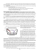


Since the vertical coverage pattern tilts
downward, we recommend little or no down-
ward horn aiming. Instead the system is aimed
by elevation; the HF horn should be elevated to
a height where it is directly in line with the last
row of seats. This has been found to provide the
best coverage front to back, and significantly
simplifies setup and installation by removing
the “guesswork” traditionally associated with
horn-aiming behind the screen.
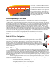
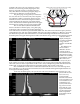
Screen compensating HF horn design
Another feature of the HF and MF horn design of the CSC Series addresses the so-called “screen
effect” of the perforation of standard perf screens. Several phenomena contribute to create a dispersion
“widening effect”. First, sound that is reflected off the rear of the screen, back into the mouth of the horn is
then passed through the screen at random angles. Also, when short wavelength frequencies pass through the
perfs, the holes themselves tend to widen dispersion, increasing with frequency beginning at frequencies
above about 5 kHz. The higher the frequency, the wider the pattern effectively becomes. However, it has
long been known the most high frequency devices tend to naturally narrow in dispersion. This “beaming
effect” has traditionally created a challenge for horn designers trying to achieve even coverage. During R&D
efforts for the CSC Series, the beaming effects of the HF driver and the widening effects created by the cinema
screen were measured with great precision by EAW engineers. As a result, the HF horn in the CSC Series
addresses this phenomenon by subtle shaping of the critical throat section of the horn,
which allows the horn to "beam" at a frequency where the effect of the screen will broaden
the coverage. The result is a more controlled high frequency dispersion pattern after the
screen.
Push-Pull LF Driver Configuration
The LF section of the CSC Series uses “push-pull” driver mounting which signifi-
cantly lowers mechanically induced distortion. Any driver will produce a certain degree
of distortion simply as a result of the motor action of the piston (voice coil/cone assembly).
When the array includes pair of identical drivers, simply inverting the mounting orienta-
tion of one driver will cause the mechanical distortion produced by one driver to “cancel”
the same distortion produced by the other. With the CSC Series, each push-pull driver pair
is loaded into its own modular enclosure, to make moving and installing the speaker easier
and less cumbersome.
EAW’s VA
4
Technology
In addition to optimized coverage, the CSC Series also features proprietary EAW design technology
which significantly improves dialogue clarity. VA
4
Technology is a breakthrough EAW design philosophy
which has been used successfully in several popular EAW professional sound systems. The main focus of
VA
4
design is how it addresses time alignment in the critical mid-band frequencies. The CSC Series’ patented
phase plug design solves problems of early arrivals in the upper mid frequency range by developing a more
logical cone geometry.
With this design, all paths from the source (voice coil) through the cone assembly (cone, dustcap and
surround) and into the horn throat are virtually identical. This subtle yet important breakthrough gives the
CSC Series its remarkably clear sound.
Cinema screen channel loudspeaker systems strive to optimize performance in four areas:
• spectral (frequency range, sound quality)
• spatial (pattern control, SPL distribution)
• temporal (unified arrivals from various subsystems)
• utilitarian (size and weight, ease of installation)
page 3