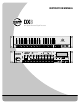
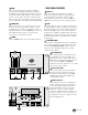
INSTRUCTION MANUAL DX8 8x2 Digital Mixer and Signal Processor OL OL OL OL OL OL OL 2 4 7 10 15 20 25 30 35 40 50 2 4 7 10 15 20 25 30 35 40 50 2 4 7 10 15 20 25 30 35 40 50 2 4 7 10 15 20 25 30 35 40 50 2 4 7 10 15 20 25 30 35 40 50 2 4 7 10 15 20 25 30 35 40 50 2 4 7 10 15 20 25 30 35 40 50 OL 15 12 9 6 3 2 4 7 10 15 20 25 30 35 40 50 0 3 6 9 12 15 DX8 DIGITAL MIXER A 1 2 3 4 5 6 7 8 LO EQ HI A MASTER B LOCK MODE B POWER COMM PORT 1 2 3 4 5 6 7 8 SERIAL NUMBER MA
CAUTION WARNING — To reduce the risk of fire or electric shock, do not expose this appliance to rain or moisture. AVIS RISK OF ELECTRIC SHOCK • DO NOT OPEN RISQUE DE CHOC ELECTRIQUE NE PAS OUVRIR CAUTION: TO REDUCE THE RISK OF ELECTRIC SHOCK DO NOT REMOVE COVER (OR BACK) NO USER-SERVICEABLE PARTS INSIDE REFER SERVICING TO QUALIFIED PERSONNEL ATTENTION: POUR EVITER LES RISQUES DE CHOC ELECTRIQUE, NE PAS ENLEVER LE COUVERCLE. AUCUN ENTRETIEN DE PIECES INTERIEURES PAR L'USAGER.
2. INTRODUCTION The DX8 is a DSP-based digital audio mixer and signal processor designed for use in a variety of installations such as churches, courtrooms, convention centers, and hotels. It provides eight universal inputs and two balanced outputs allowing true 8x2 mixing for stereo or dual-zone applications. The DX8 includes powerful signal processing software to complement the 8x2 mixing structure. Automixing capability allows the DX8 to be setup for applications where a human operator is not available.
FRONT PANEL FEATURES INPUT UP/DOWN BUTTONS Use these buttons to adjust the mix level for each input channel. INPUT LED DISPLAY This indicates the signal level after the mic preamp stage, just after the A/D converter, but prior to any digital signal processing. When any input UP/ DOWN button is pressed, all the meters (except EQ) switch from level metering to level setting indication. After five seconds, the meters switch back to normal peak program metering (PPM).
MODE This switch changes the front panel operation between Bus A and Bus B operation. In addition, the LOCK position disables the front panel controls to prevent unauthorized changes to the settings. A security code must be entered to enable the front panel controls when the DX8 is locked. See page 17 for more information on locking and unlocking the DX8.
RECORD Out These RCA connectors supply unbalanced line-level signals from the BUS A and BUS B outputs. Use these outputs to connect to the inputs of a recorder, or as additional line-level outputs to connect to an external power amplifier. The signals are the same as the main outputs. OUTPUTS A/B These 3-pin Phoenix-type connectors supply a balanced line-level signal from BUS A and BUS B. LOGIC I/O This 25-pin D-Sub connector provides 10 logic control inputs and 10 logic control outputs (opencollector).
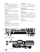
LISTED COMMERCIAL AUDIO EQUIPMENT 9Z39 , 50/60Hz, 1A MAX – + LINE LINE + G – MIC + G – BUS A A: Typical Stereo Application R 100 – 240V POWER INPUT 22-28V DC, 3A MAX +20 TRIM -20 U LINE BUS B +20 TRIM -20 U DIRECT OUTPUTS 1 2 3 4 5 6 7 8 Microphone U 3 LINE MIC TRIM 0 60 -30dB +30dB C GAIN MI U 4 LINE MIC TRIM 0 60 -30dB +30dB C GAIN MI Left Stereo Power Amplifier LINE MIC MIC LINE TRIM TRIM 2 0 60 -30dB +30dB 0 60 -30dB +30dB 1 U C GAIN MI U C GAIN MI D
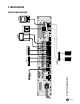
– DX8 + – + LINE LINE G + – – MIC + G BUS A LINE TRIM +20 BUS B -20 U Zone A (Restaurant) 70V Distribution Power Amplifier LISTED COMMERCIAL AUDIO EQUIPMENT 9Z39 , 50/60Hz, 1A MAX POWER INPUT 22-28V DC, 3A MAX +20 TRIM -20 U DIRECT OUTPUTS 1 2 3 4 5 6 7 8 Paging Mic B: Typical Two-Zone Application –10 –8 –6 –3 0 – 5 – 10 – 15 – 20 – 25 – 30 – 40 R 100 – 240V 24VDC Power Supply Zone A Remote Controls – Priority Enable Priority Mic Control Switch to Logic Input LINE MIC M
Drum Mics Vocals Laptop with DX8-PC Application Vocals Vocals Wireless Microphone Receiver for Lead Vocalist Digital Multitrack Recorder Optional Live Recording 1 2 3 4 5 6 7 8 SERIAL NUMBER MANUFACTURING DATE DX8 DIGITAL MIXER DIRECT OUTPUTS U U U U U U U U U U C GAIN MI C GAIN MI C GAIN MI C GAIN MI C GAIN MI C GAIN MI C GAIN MI C GAIN MI 0 60 -30dB +30dB 0 60 -30dB +30dB 0 60 -30dB +30dB 0 60 -30dB +30dB 0 60 -30dB +30dB 0 60 -30dB +30dB 0 60 -30dB +30dB 0 60 -30dB +30dB
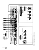
– DX8 – + 70V Distribution Power Amplifier LISTED COMMERCIAL AUDIO EQUIPMENT 9Z39 , 50/60Hz, 1A MAX +20 Zone A LINE – MIC + G LINE G + – BUS A TRIM -20 U LINE BUS B +20 TRIM -20 U DIRECT OUTPUTS 1 2 3 4 5 6 7 8 Podium Mic D: Board Room Application with Two-Zones –10 –8 –6 –3 0 – 5 – 10 – 15 – 20 – 25 – 30 – 40 Zone A Remote Controls R 100 – 240V POWER INPUT 22-28V DC, 3A MAX Priority Enable Priority Mic Control Switch to Logic Input LINE MIC MIC LINE TRIM TRIM 2 0 6
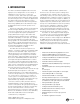
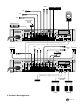
Application Diagrams A: Typical Stereo Application This diagram depicts a simple setup, using the DX8 in a stereo application. A microphone is connected to the MIC input on channel 1 for paging purposes, and several program sources are connected to the LINE inputs on channels 3 through 8. B: Typical Two-Zone Application This configuration demonstrates how the DX8 might be used in a restaurant/bar application. A paging mic is connected to the MIC input on channel 1.
CONNECTIONS Connecting Balanced Sources Connecting Unbalanced Sources Use high-quality three-conductor cable for balanced connections, such as Star Quad by Belden, Canare, Mogami, etc. The better the shield, the better the audio signal is protected from induced EMI and RFI. Note: With screw-down connectors, it's best to use stranded wire that is not tinned. Solder can "flow" under the pressure of the screw-down terminal and cause the connection to become loose.
Strip the wire back about 1/4" inch, insert the wire as far as it will go into the appropriate hole in the supplied Phoenix-type connector, and tighten down the screw with a small slot-head screwdriver. It is recommended that you use 20 or 22 gauge wire with the Phoenix-type connectors.
4. OPERATION QUICK START Reading the instruction manual is the only way to fully understand the features and functions of the DX8. However, the Quick Start provides a quick overview to get the DX8 set up and working fast. Make sure the power switch is off while setting up and making connections to the DX8. Make the Connections Determine which inputs to use for MIC program sources and which to use for – + G microphones. Follow the wiring diagram on the rear panel to make the connections.
USING INPUTS 1-8 Bus A and B Input Trim There is no metering after the BUS A and B input TRIM controls. These controls must be adjusted by ear. Start the program source playback for all sources connected to the BUS A or BUS B input. Slowly increase the TRIM control to the center position (12 o'clock), which is unity gain. Then adjust the TRIM control up or down to attain a balance within the total mix.
DIRECT OUTPUTS The DIRECT OUTPUTS provide an unbalanced linelevel signal from each of the 8 Input channels. This signal comes from the output of the preamplifier stage on each input channel, prior to the A/D converter and subsequent digital signal processing. Use the DIRECT OUTPUTS to connect a continuous music source (e.g., satellite feed, prerecorded background music, multi-disc CD player).
The logic functions assigned to each individual logic input and output are configured using the DX8PC application. In addition, each logic input and output can be assigned a descriptive name (up to 32 characters) for easier identification within the PC application. Note: Logic I/O functions are set from the PC application only.
FRONT PANEL LOCK The MODE button on the front panel is used to disable the front panel controls by selecting LOCK. The LOCK LED blinks for about five seconds before it engages. When the LED lights steadily, the front panel controls are disabled. The Lock Code is set using the DX8-PC application (see page 20, "Set Lock Code").
OVERVIEW The DX8-PC software application provides real-time control and configuration editing for the DX8 using a laptop or other PC-compatible computer.
Advanced To save a configuration file: 1. Click Select File in the Configuration File window. 2. Browse to the location where you want to save the file in the Select Configuration File window. 3. Enter a new name in the File Name box and click Open. 4. Click PC ← DX8 to save all the current settings of the DX8 to the PC. The Status box will indicate if the file was successfully saved to the selected location.
Windows Compressor This toggles the Compressor window open and closed. It duplicates the function of the Compress button under DSP on the right side of the screen. Audio Input This toggles the Audio Input window open and closed. It duplicates the function of the Audio In button under Setups on the right side of the screen. Logic Input This toggles the Logic Input window open and closed. It duplicates the function of the Logic In button under Setups on the right side of the screen.
Presets Clear Edits The DX8 stores up to 16 presets, which can be recalled via the Presets drop-down box. Select a preset in the drop-down box and the settings are instantly recalled from the DX8 memory. Click this button to restore the DX8 settings to the currently selected preset. On Line Click this button to initiate communication with the DX8. This button lights to indicate when there is active communication between a DX8 and the PC. Click this button again to terminate communication.
BUTTONS Views These four buttons open the Graphic EQ, Parametric EQ, Output Compressor, and Automix views, overlaid across the input section. Graphic EQ Click this button to open the 31-Band Graphic Equalizer window for the A and B outputs. Click and drag on a slider knob to adjust the EQ. The selected band’s GAIN and BAND (frequency) are displayed at the top of the window. Click the ON button to turn each Graphic EQ on and off.
Compress • Ratio: This determines the change in output level as a function of the change in input level, once the threshold has been exceeded. It is calibrated in decibels, with a range from 1:1 (off) to 20:1. Thus, if it is set to 10:1, an increase in input level of 10 dB (assuming the input is above the threshold level), results in a 1 dB increase in output level. As a general rule, use ratio settings from 1:1.5 to 1:5 for compressor use.
Each individual channel is attenuated by an amount, in dB, equal to the difference, in dB, between that channel’s level and the sum of all the channel levels. This keeps the overall system gain constant, and allows the system to deliver maximum acoustic gain without feedback. There are three parts to the automixing feature in the DX8. AUTO: This button turns Automixing on or off for an individual channel in the Mix A or Mix B output. This also enables the automatic gating feature.
Use a control group to adjust the volume of two or more channels at the same time. All faders that are assigned to a control group will have their gain settings modified by the amount the control group fader is increased or decreased. For example, a control group might be used to adjust the overall volume for all the choir mics in a church by configuring a Level Remote Control to adjust the volume on a control group to which all the choir mics are assigned.
Action Definitions Momentary means that the logic function is active as long as the Logic Input is held active. When the Logic Input is inactive, the logic function is inactive. Latch On means that the logic function is active and stays active once the Logic Input changes from inactive to active (logic high to logic low). Changing the Logic Input from active to inactive does not affect the logic function—it stays latched on.
Another application might be to turn on an amplifier when an output signal is present. Connect the Output Signal Present logic output to a power controller or power-up sequencer that switches AC power to the amplifier's AC line cord. Input Channel Open: This can be used to provide a visual indication (via an LED) that a microphone's gain is turned up and ready to use. Note that if a channel is muted, the Input Channel Open logic pin will become inactive (logic high).
Output Strip Meter The output meter indicates the output signal level just after the output gain control and just prior to the D/A converter stage. These meters indicate the signal level in real time relative to maximum output level (+18 dBu) and follow the meters on the front panel, with the exception that they don't indicate gain when the Up/Down buttons are pressed, as the front panel meters do.
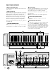
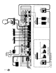
– DX8 LINE CHANNEL 1 DX8 OR eNET16 HUB (OPTIONAL) PC OR OTHER CONTROL DEVICE (OPTIONAL) LOGIC IN (1 OF 10) DIRECT OUTPUT +5V eNET16 CARD (OPTIONAL) FRONT PANEL COMM PORT TRIM ADC 24-BIT MUTE CONTROL PROCESSING CHANNELS 2-8 (IDENTICAL TO CH 1) 3-BAND INPUT EQ 32-BIT DSP INPUT METER A +5V REMOTE CONTROL REAR PANEL COMM PORT B ALC ALC REMOTE CONTROL (OPTIONAL) PC OR OTHER CONTROL DEVICE (OPTIONAL) LOGIC OUT (1 OF 10) ALC ALC REMOTE CONTROL (OPTIONAL) AUTO AUTO AUTOMIX GAIN
DX8 SPECIFICATIONS INPUTS / OUTPUTS SIGNAL PROCESSING Inputs 1-8: Balanced, Phoenix-type terminals Bus A and B: Balanced, Phoenix-type terminals, Direct to Mix Buses Master Outputs: Balanced, Phoenix-type terminals Record Outputs A/B: Unbalanced, RCA Direct Outputs 1-8: Unbalanced on DB15 (bottom row is signal return) Logic Inputs: 10 Inputs on DB25 Series resistance: 570Ω Internal pull-up: 47kΩ to +5V DC Input voltage: +5.5V DC maximum Active voltage: +1.
Crosstalk (1kHz relative to 0 dBu, 20Hz-20kHz bandwidth, any line input to adjacent Direct Out): Trim to unity: < –90 dB Frequency Response Mic input to any output: PHYSICAL Dimensions (HxWxD): 3.5"/2RU (89mm) x 19" (483mm) x 13.25" (337mm) Net Weight: 17 lbs. (7.7 kg) 20Hz–20kHz, ±0.5 dB Equivalent Input Noise (EIN) Mic in to Direct out, max gain, 150 ohm termination: –129.
DISCLAIMER 7. SERVICE INFORMATION EAW Commercial continually engages in research related to product improvement, new materials, and production methods. Design refinements are introduced into existing products without notice as a routine expression of that philosophy. For this reason, any current EAW Commercial product may differ in some respect from its published description, but will always equal or exceed the original design specifications unless otherwise stated.
Appendix A: Logic Input Functions Logic Input Function Inactive Force-On Force-Off Mute Input Mute Output Action None Momentary None Momentary None Momentary Latch On Latch Off Toggling Momentary Latch On Latch Off Toggling Mute Group Preset Recall Momentary Latch On Latch Off Toggling Momentary Latch On Affected I/O None Input 1 to Input 8 Input 1 to Input 8 Input 1 to Input 8 Input 1 to Input 8 Input 1 to Input 8 Input 1 to Input 8 Input 1 to Input 8 Input 1 to Input 8 Output A Output B Output A&
Appendix C: Selection Remote Predefined Functions DX-SW4 Remote Switch Control (4-button/4-LED) Switch Positions ID 1 through 8 0 00000000 1 10000000 2 01000000 3 11000000 4 00100000 5 10100000 6 01100000 7 11100000 8 00010000 9 10010000 10 01010000 11 11010000 12 00110000 13 10110000 14 01110000 15 11110000 16 00001000 17 10001000 18 01001000 19 11001000 20-255 Function Mute Input 1-4 (1) Mute Input 1-4 (2) Mute Input 5-8 (1) Mute Input 5-8 (2) Mute Group 1-4 (1) Mute Group 1-4 (2) Mute Group 5-8 (1) Mute
EAW Commercial A LOUD Technologies Inc. Company EAW Commercial | Bldg 11 | One Main Street | Whitinsville, MA 01588 USA | TEL toll free within US/Canada 888.337.7404 TEL outside US 425.892.6503 | FAX 425.485.1152 | www.eawcommercial.com © 2004 LOUD Technologies Inc. All Rights Reserved.