INSTRUCTION MANUAL DX810 v3.
CAUTION WARNING — To reduce the risk of fire or electric shock, do not expose this appliance to rain or moisture. AVIS RISK OF ELECTRIC SHOCK • DO NOT OPEN RISQUE DE CHOC ELECTRIQUE NE PAS OUVRIR CAUTION: TO REDUCE THE RISK OF ELECTRIC SHOCK DO NOT REMOVE COVER (OR BACK) NO USER-SERVICEABLE PARTS INSIDE REFER SERVICING TO QUALIFIED PERSONNEL ATTENTION: POUR EVITER LES RISQUES DE CHOC ELECTRIQUE, NE PAS ENLEVER LE COUVERCLE. AUCUN ENTRETIEN DE PIECES INTERIEURES PAR L'USAGER.
2. INTRODUCTION The DX810 is our popular DX8 stereo digital audio mixer with the DX10e Expansion Kit installed. This adds eight more balanced outputs and converts it into a powerful matrix mixer/processor. It is designed for use in a variety of installations such as churches, courtrooms, convention centers, and hotels. With eight inputs, ten outputs, and a toolbox full of DSP, the DX810 fits most any installed sound reinforcement application.
KEY FEATURES • Room Combining with up to 16 different combinations available 2 balanced Line inputs direct to mix buses A and B • 10 Programmable Logic Inputs • 10 Independent Mix Buses and balanced Outputs • 10 Programmable Logic Outputs • 2 unbalanced Record Outputs • 2 independent RS-232 interface ports • 8 unbalanced Direct Channel Outputs • 48 VDC Phantom Power switch per input Individual Level/Peak (PPM) metering on each Input • 24 VDC Backup Power input • 2-band sweepable shelvin
FRONT PANEL FEATURES Note: The front panel controls only apply to the A and B outputs. Outputs C through J are controlled with the DX-810-PC software interface. INPUT UP/DOWN BUTTONS Use these buttons to adjust the mix level for each input channel. INPUT LED DISPLAY This indicates the signal level after the mic preamp stage, just after the A/D converter, but prior to any digital signal processing.
TRIM This rotary analog control is used to trim the gain of the input signal for optimum signal-to-noise ratio in the preamp stage. For mic-level signals, it provides from 0 to +60 dB of gain. For line-level signals, it provides from –30 dB to +30 dB of gain. Unity (0 dB) is at the center position. This control accepts a maximum input signal of +18 dBu before clipping (at unity gain). OUTPUTS A/B These 3-pin Phoenix-type connectors supply a balanced line-level signal from OUTPUTS A and B.
The DIRECT OUTPUT connector is wired as follows: 3. INSTALLATION CONNECTIONS DIRECT OUTPUTS SIGNAL RETURN SIGNAL RETURN SIGNAL RETURN SIGNAL RETURN SIGNAL RETURN SIGNAL RETURN SIGNAL RETURN Connecting Balanced Sources Use high-quality three-conductor cable for balanced connections, such as Star Quad by Belden, Canare, or Mogami, etc. The better the shield, the better the audio signal is protected from induced EMI and RFI.
Connecting the LOGIC I/O LOGIC OUT This is a 25-pin D-Sub connector. There are 10 programmable logic inputs and 10 programmable logic outputs. In addition, there is an 11th fixed logic output to indicate "System OK." They are all activelow circuits. Use 22 gauge wire for these connections.
4. OPERATION QUICK START Set the Levels Reading the instruction manual is the only way to fully understand the features and functions of the DX810. However, this Quick Start section provides a quick overview to get the DX810 set up and working fast. Make sure the power switch is off while setting up and making connections to the DX810. Make the Connections MIC – + G Determine which inputs to use for program sources and which to use for microphones.
USING INPUTS 1-8 Bus A and B Input Trim There is no metering after the BUS A and B input TRIM controls. These controls must be adjusted by ear. Start the program source playback for all sources connected to the BUS A or BUS B input. Slowly increase the TRIM control to the center position (12 o’clock), which is unity gain. Then adjust the TRIM control up or down to attain a balance within the total mix at the A and B outputs.
USING THE DIRECT OUTPUTS The DIRECT OUTPUTS provide an unbalanced linelevel signal from each of the 8 Input channels. This signal comes from the output of the preamplifier stage on each input channel, prior to the A/D converter and subsequent digital signal processing. Use the DIRECT OUTPUTS to connect a continuous music source (e.g., satellite feed, prerecorded background music, or multi-disc CD player). This may connect to a telephone system music-on-hold input.
The logic functions assigned to each individual logic input and output are configured using the DX810-PC application. In addition, each logic input and output can be assigned a descriptive name (up to 32 characters) for easier identification within the PC application. Note: Logic I/O functions are set from the PC application only.
Preset Active A logic output can indicate when a particular preset is active. Force On A logic output can indicate when a particular input or group is being forced on. Priority active A logic output can indicate when a particular input or group force-on priority is active. Combine active A logic output can indicate when a particular combination (combine) is active. Gate Status A logic output can indicate when a particular Input Gate is open. Note: An input gate that is disabled (off) is always open.
Important! CONNECTING A PC Use a standard DB9 (male/female) computer cable to connect a PC to the DX810. The DX-810-PC application uses COM1 on the PC by default. You can select a different COM port by clicking on Advanced in the top menu bar and selecting Configure COM Ports. Refer to “Configure COM Ports” on page 16 for more information. Connect the COM port on the PC to one of the COMM PORTs on the DX810 (front or rear).
TOP SECTION Edit The Top Section includes the Menu bar, the Active Logic Input and Output indicators, and Preset, On Line, and Panel Lock controls. Menu Bar The following menus are available in the Menu bar at the top of the screen: File Open (Ctrl+O) Opens a previously saved session. The Select Workspace File dialog box opens and allows you to select a session to open. Select a file and click Open, or double-click on the file to open it.
Firmware Upgrade This allows you to select an OS upgrade file to upload to the DX810 as they become available. Click Select File in the Firmware Upgrade window and the Select OS Upgrade File dialog box opens. Browse to the location of the OS upgrade file (with a .pkt extension) on your hard drive or floppy drive and click Open, then click Upgrade. You can monitor the progress in the Firmware Upgrade window.
Note: When changing presets, the faders change position quickly on-screen, but the audio actually ramps according to the Ramp Time setting. Set Powerup Preset Select this to open the Powerup Preset Selection window. When None (last state) is selected, the DX810 returns to its state when it was last turned off. Click in the Select Powerup Preset box and drag up or down to select one of the 24 presets to load on powerup.
Output EQ This toggles the Output EQ window open and closed. It duplicates the function of the Output EQ button in the Button Section. Compressor This toggles the Compressor window open and closed. It duplicates the function of the Compress button in the Button Section. Gate This toggles the Gate window open and closed. It duplicates the function of the Gate button in the Button Section. Delay This toggles the Delay window open and closed.
Button Section The Button Section includes the assignment buttons (Force Ctrl, Logic In, Logic Out, Groups, Input Proc, Out Proc, Mute Ind) and the DSP buttons (Combine, Input EQ, Output EQ, Compress, Gate, Delay, X-Over). Assignments Force Ctrl Click this button to open the Force Control window. Input Name: Enter a name for each channel with the keyboard. It will accept up to 32 characters. Force On Level: Assign a force-on level to each input, from OFF to +10 dB.
Logic Out Click this button to open the Logic Output window. Make the following settings and assignments in the Logic Output window: Name: Enter a name for each Logic Output, up to 32 characters. Function: Select one of 10 different functions in this drop-down box. These functions include Inactive, Input/Mute Enable, Output Signal Present, Preset Active, Output/Mute Enable, Group/Mute Enable, Force On, Priority Active, Combine Active, and Gate Status.
Mute Ind Click this button to view the Active Mute Groups indicator in the upper left corner of the screen. If a group mute button is active, the associated indicator lights up in the Active Mute Group indicator. Remotes Click this button to open the Remote Mapping window. Four buttons along the top of this window allow selecting 16 DX-SW4 remotes in groups of four. The four selected remotes (addresses 41-44, 45-48, 49-52, and 53-56) appear in the Remote Mapping window.
3. Combining only affects crosspoints and outputs that are assigned to control groups (see rule 1). Any crosspoint or output that is part of a combination, but is not assigned to a control group, will be muted when the combination is inactive, and audible when the combination is active. 4. Multiple combinations can be activated at the same time. 5. Outputs that are not assigned to any combinations are not affected by these rules.
is created, activated, and then deactivated. That is when the combine rules take effect. Assign Combinations Now we’ll create the combination to allow the inputs for rooms A and B to be heard in both A and B outputs when C1 is active. 11. Open the combine view by clicking on the Combine button. Tip: Each row of combine buttons (C1-C16) is associated with the output at the end of the row. There is no association with the inputs or input faders at the bottom (vertically).
Output EQ Click this button to view the Output EQ controls. Click the output letter buttons (A-J) to select an output after the Output EQ window is open. Select either a 31-band Graphic EQ or an 8-band Parametric EQ. Note: When switching between the 31-band Graphic EQ and the 8-band Parametric EQ, a warning will appear: "This will reset all EQ parameters!" Click Cancel to retain the current EQ settings, or OK to change EQ modules.
• Ratio: This determines the change in output level. It is a function of the change in input level (at full compression), once the threshold has been fully exceeded. It is calibrated in decibels, with a range from 1.0:1 (off) to 20:1. Thus, if it is set to 10:1, an increase in input level of 10 dB results in a 1 dB increase in output level. This assumes the input is above the threshold level. Generally, use ratio settings from 1.5:1 to 5.0:1 for compressor use.
reflected in the Crosspoint Matrix Section by “blanking out” all but the top row of crosspoints for the linked crossover outputs. Note that only contiguous outputs may be linked to create a crossover. Linking outputs together for the crossover automatically links those outputs in Output EQ processors. The Output EQ defaults to the setting for the first output in the crossover (i.e., Output A).
INPUT SECTION OUTPUT SECTION This section includes the eight input faders along with their associated bargraph input level meters, Select and Mute buttons, and name box. The Output Section includes the ten output faders along with their associated bargraph output level meters. This section also includes numerical gain display, mute and solo buttons, and name box. Use the output faders to adjust the final output level of the signal.
Click the letter button when a processing window is showing (except Gate and Input EQ) to adjust the processing options for that output. Use the box to the right of the Output Section to enter a name for the output (e.g., Main Left, Control R), using up to 32 characters. GROUP SECTION This section includes the 32 control groups. Eight groups are displayed at one time. However, the horizontal fader at the bottom allows you to scroll through all the control groups.
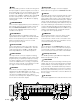
LINE CHANNEL 1 MIC +48 VDC PC OR OTHER CONTROL DEVICE (OPTIONAL) LOGIC IN (1 OF 10) DIRECT OUTPUT PHANTOM POWER +5V FRONT PANEL COMM PORT TRIM ADC 24-BIT GATE CONTROL PROCESSING INPUT METER 32-BIT DSP COMPRESSOR REMOTE CONTROL REAR PANEL COMM PORT +5V REMOTE CONTROL (OPTIONAL) TO ADDITIONAL REMOTE CONTROLS (OPTIONAL) D C B A MUTE/ENABLE MUTE/ENABLE MUTE/ENABLE MUTE/ENABLE DELAY DELAY DELAY DELAY BUSES E-J (IDENTICAL TO A-D) 8b 31b 8b 31b 8b 31b 8b 31b BUS B INPUT
DX810 SPECIFICATIONS INPUTS / OUTPUTS SIGNAL PROCESSING Inputs 1-8: Balanced, Phoenix-type terminals Bus A and B: Balanced, Phoenix-type terminals, Direct to Mix Buses Outputs A-J: Balanced, Phoenix-type terminals Record Outputs A/B: Unbalanced, RCA Direct Outputs 1-10: Unbalanced on DB15 (bottom row is signal return) Logic Inputs: 10 Inputs on DB25 Series resistance: 570Ω Internal pull-up: 47 kΩ to +5 VDC Input voltage: +5.5 VDC maximum Active voltage: +1.
AUDIO Noise (20 Hz-20 kHz bandwidth, Master Out, channel Trims @ unity gain, channel EQs flat, all odd channels panned left, even channels panned right): Master level @ unity, channel levels @ unity: –82 dBu Single channel to Master Out: –100 dBu (referenced to 1% THD+N) Total Harmonic Distortion (THD+N) (1 kHz @ +10 dBu (unity level) 20 Hz-20 kHz): Mic in to Master Out: < 0.
DISCLAIMER 7. SERVICE INFORMATION EAW Commercial continually engages in research related to product improvement, new materials, and production methods. Design refinements are introduced into existing products without notice as a routine expression of that philosophy. For this reason, any current EAW Commercial product may differ in some respect from its published description, but will always equal or exceed the original design specifications unless otherwise stated.
Appendix A: Logic Input Functions Logic Input Function Inactive Force-On Force-Off Mute/Enable Input Mute/Enable Output Mute/Enable Group Preset Recall Combine Action None Momentary Latch On Latch Off Toggling Momentary Latch On Latch Off Toggling Momentary Latch On Latch Off Toggling Momentary Latch On Latch Off Toggling Momentary Latch On Latch Off Toggling Momentary Latch On Momentary Latch On Latch Off Toggling Affected I/O None Input 1-8; Group 1-32 Input 1-8; Group 1-32 Input 1-8; Group 1-32 In
Appendix C: Selection Remote Predefined Functions DX-SW4 Remote Switch Control (4-button/4-LED) for DX-810 v3.3 (Firmware v7.
Appendix D: Level Remote Predefined Functions DX-RVC Remote Volume Control (2-button/12-LED) ID 0 1 2 3 4 5 6 7 8 9 10 11 12 13 14 15 16 17 18 19 20 21 22 23 24 25 26 27 28 29 30 31 32 33 34 35 36 37 38 39 40 41 42 43 44 45 46 47 48 49 50 51 52 53 54 55 56 57 58 59 60 Switch Positions 1 through 8 00000000 10000000 01000000 11000000 00100000 10100000 01100000 11100000 00010000 10010000 01010000 11010000 00110000 10110000 01110000 11110000 00001000 10001000 01001000 11001000 00101000 10101000 01101000 111010
EAW Commercial A LOUD Technologies Inc. Company EAW Commercial | Bldg 11 | One Main Street | Whitinsville, MA 01588 USA | TEL toll free within US/Canada 888.337.7404 TEL outside US 425.892.6503 | FAX 425.485.1152 | www.eawcommercial.com © 2004 LOUD Technologies Inc. All Rights Reserved.