
Specifications

EAW Smaart 6 Operation Manual Analysis Modes and Display Types
52
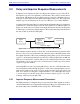
3.3 Delay and Impulse Response Measurements
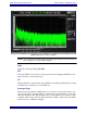
In Impulse mode, Smaart 6 measures and displays the impulse response of the SUT.
The impulse response is used primarily to find the time offset (delay) between the two
input signals. The Impulse mode plot displays energy versus time rather than energy vs.
frequency as in the analyzer modes (RTA and Frequency Response). The result of the
impulse response measurement can be stored as a Windows .wav or Mac AIFF file.
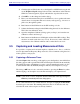
As with real-time Frequency Response measurements, the Impulse Response calculations
assume the two sound card inputs receive the same signal but over different paths (see
Figure 3-9). Audio data is recorded from the inputs then transformed into the frequency
domain and processed using a transfer function. The result is then transformed back into
the time domain by an Inverse FFT (IFT).
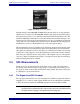
Figure 3-9 Block Diagram of a Delay or Impulse Response Measurement
This technique requires the time constant (TC) of the measurement (sometimes called
the time window) to be longer than the total of the decay time of the SUT plus the entire
throughput delay time of the system, including the time it takes sound to travel from the
source to your measurement microphone. Since TC = FFT size/SR, if SR = 48 kHz and
FFT size = 32,768, then TC = 683 ms. This provides a sufficient time window for small
and medium rooms. Large and/or very reverberant spaces (with longer decay times)
require a longer time window.
Increasing FFT size and/or decreasing SR increases the size of TC. Remember that
decreasing SR also limits the high frequency content of the resulting impulse response
(this may be useful in some cases). If you are unsure about the decay time of the room/
SUT, err on the side of setting TC too high rather than too low. Although it takes longer
to record and process the data and produces an unnecessarily long noise tail, each
doubling of TC increases the S/N 3 dB.
3.3.1 Impulse Response Measurement Parameters
The FFT parameters for Impulse Response measurements differ slightly from those
offered in Real-time mode for Spectrum and Frequency Response measurements. Note
the relationship between the FFT and TC settings (TC = FFT size/SR).
Reference Signal
Measurement
Signal
Device or
System
Under Test
Computer
Signal
Source