
Specifications


EAW Smaart 6 Operation Manual Analysis Modes and Display Types
63
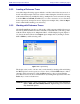
3.6 Internal Delay
Smaart 6 can provide up to 750 ms of signal delay internally for one of the two input signals.
This feature is primarily intended to provide signal alignment between the reference and
measurement signals in Frequency Response measurements. Delay properties are set
from the Delay tab of the Options dialog box, accessed by choosing Options->Delay or
by clicking the Delay button. Input channel assignment is normally set to the reference
signal channel. See page 99 for a full explanation of the Delay options.
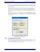
Smaart 6’s internal delay is neatly integrated with the Delay Auto-Locator and Impulse
mode operations. Each time the Delay Auto-Locator runs, the delay time found can be
assigned to the internal delay upon completion. Set a Locked Cursor by Ctrl-clicking at
the desired location on the plot. Click the Delay button or select Options->Delay to
display the Delay tab of the Options dialog box with the Locked Cursor location entered
as the current Delay Time value.
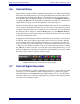
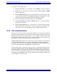
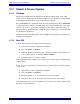
In Impulse mode, the Delay Presets have another function. Notice that on-screen buttons
for the five delay preset registers appear below the plot when you switch to Impulse
mode. Clicking on the readout field below the button for any delay preset with your
mouse in produces a pop-up menu that lets you assign the current Locked Cursor location
to that preset (and display its marker on the plot) or bring up Delay Options. Clicking
the A-E buttons with your mouse or pressing the corresponding Function key on your
keyboard in Impulse mode will plot a vertical line on the impulse response plot to mark
the time position of the associated stored delay value.
Figure 3-16 Delay Presets in Impulse Response window
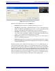
3.7 Internal Signal Generator
If your sound hardware is capable of full-duplex operation (i.e., play and record simul-
taneously) you can use Smaart 6’s built-in signal generator to generate test signals.
Click the field below the Generator button (right of Figure 3-17) to open the Signal
Generation dialog box to adjust the signal generator’s properties. The signal generator
can create several stimulus signals.