
Specifications


EAW Smaart 6 Operation Manual Applications
75
4.2.1 Measurement Setup
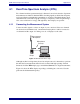
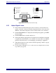
Connect all the components as shown in Figure 4-5. The computer’s line level output
drives both the equalizer’s input and the sound card’s reference input. The equalizer’s
output is routed to the computer through the sound card’s measurement input. Smaart
6’s internal signal generator excites the equalizer and the generator output is compared
to the output from the equalizer, effectively canceling any imperfections introduced by
the sound card. The resulting transfer function represents the difference between the
reference and measurement inputs.
Figure 4-5 Analog EQ measurement setup
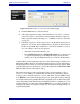
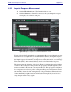
4.2.2 Adjusting Signal Levels
1. If pink noise is not already selected for the noise generator, open the Signal
Generation dialog by clicking anywhere on the Generator readout.
2. Select Pink Noise from the Signal list.
3. Enter a generator level of around -6 dB into the Level1 field. The generator
defaults to a low output level (-36 dB) so increase it by either typing the level
or using the up/down arrows to adequately utilize the dynamic range of the
system and equalizer.
4. Select the Generator ON checkbox and click OK to exit the dialog. The Generator
button’s LED illuminates and pink noise is generated from the sound card output.
Measurement Signal
Reference Signal
Computer
Line Out
Equalizer