Drawing : - TPC229 Issue :-2 Date : - 10/12/13 LUMBER DRYER LD3000 OWNER’S MANUAL www.eipl.co.
Drawing : - TPC229 Issue :-2 Date : - 10/12/13 INTRODUCTION You have probably never seriously considered kiln drying your own lumber before, believing it to be too expensive or too complicated to undertake on a small scale. Prior to the introduction of the Ebac Small Scale Lumber Dryers this was true.
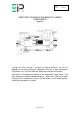
Drawing : - TPC229 Issue :-2 Date : - 10/12/13 SIMPLIFIED SCHEMATIC DIAGRAM OF LUMBER COMPONENTS Figure 2 Though the fastest drying is achieved at high temperature, the risks of degrade in the wood, particularly hardwood, increases at high temperature. The general rule is that the lower the temperature the better the quality. Ebac dryers are designed to operate in the temperature range, which is the best compromise between speed and quality – about 140°F (60°C) and lower.
Drawing : - TPC229 Issue :-2 Date : - 10/12/13 UNPACKING Upon receipt of your LD3000, carefully inspect the shipping container and its contents for any damage. If damage is discovered, contact the Service Department for instructions. CONTENTS Your LD3000 shipment consists of the following items: 1. 2. 3. 4. 5.
Drawing : - TPC229 Issue :-2 Date : - 10/12/13 DRYER CAPACITIES Table 1 below shows average drying times for the LD3000. Table 2 shows the optimum load capacities for the LD3000. If larger quantities than those shown in Table 2 are dried, drying speed will be proportionately slower. If small quantities are dried, the controls can be adjusted to allow for this.
Drawing : - TPC229 Issue :-2 Date : - 10/12/13 KILN CHAMBER LUMBER STACK SIZE The first step in determining your kiln chamber size is to determine the most suitable lumber stack size (or configuration) for your purposes. This will depend primarily on the longest length board to be dried. Normally, the length of the stacks will be equal to the length of the longest board. If you lumber is in short lengths (i.e.: approximately 3 feet), then the stack length should be multiples of these lengths.
Drawing : - TPC229 Issue :-2 Date : - 10/12/13 CHAMBER INTERIOR DIMENSIONS Having calculated the stack size, it is now possible to calculate the appropriate internal dimensions of the chamber. This is done by adding the required additional space around the stack for the dryer and the fans as well as for good air circulation.
Drawing : - TPC229 Issue :-2 Date : - 10/12/13 CHOOSING PROPER INSULATION THICKNESS The wall thickness (insulation) is very important and is related to the size (surface area) of the chamber. After adding the required internal clearances to the stack size, the internal dimensions are known, and the approximate chamber surface area can be calculated. Table 3 shows the recommended thickness of insulation (wall thickness) in relation to the total surface area of the walls, ceiling and floor of the chamber.
Drawing : - TPC229 Issue :-2 Date : - 10/12/13 EXAMPLE KILN SIZES If you would rather not design the dimensions of you kiln, simply choose the best size for you operation from Table 4. All of the kiln dimensions shown are exterior dimensions. The load sizes refer to 1” hardwood with ¾” stickers, and all the wall thickness and air spaces have been added in.
Drawing : - TPC229 Issue :-2 Date : - 10/12/13 CONSTRUCTION OF CHAMBER Floor: An insulated concrete floor is recommended. • • • • Notes: Start with a gravel base. Lay down 2” of rigid Styrofoam. Pour 4” of reinforced concrete. Seal concrete with any commercially prepared sealer A slightly pitched floor leading to drain may be incorporated. This will helpful if large amounts of softwood are to e dried. Should an insulated concrete floor not be feasible, a well-built, insulated wooden floor will work.
Drawing : - TPC229 Issue :-2 Date : - 10/12/13 Door Construction: • • • The door section should be constructed the same as the walls and ceiling. Exterior plywood should overlap the door frame by 3”. This will allow space to attach a rubber gasket and enable the door to be bolted to the kiln chamber. Anchor bolts are recommended for continued usage. For front loading kilns, hinged double doors are needed. See Figures 6 and 7.
Drawing : - TPC229 Issue :-2 Date : - 10/12/13 Page 12 of 40
Drawing : - TPC229 Issue :-2 Date : - 10/12/13 Page 13 of 40
Drawing : - TPC229 Issue :-2 Date : - 10/12/13 Page 14 of 40
Drawing : - TPC229 Issue :-2 Date : - 10/12/13 Page 15 of 40
Drawing : - TPC229 Issue :-2 Date : - 10/12/13 Page 16 of 40
Drawing : - TPC229 Issue :-2 Date : - 10/12/13 Page 17 of 40
Drawing : - TPC229 Issue :-2 Date : - 10/12/13 INSTALLATION AND TESTING Installation All wiring should be carried out by a competent electrical contractor in accordance with local regulations. The 16-inch circulation fans do not connect to the STC1 Controller. They must be connected to separate switchgear. Warning: OSHA complying guards are strongly recommended when fans are installed with 7’ of floor, working level, or within reach of personnel. Review OSHA codes.
Drawing : - TPC229 Issue :-2 Date : - 10/12/13 TESTING FOR PROPER INSTALLATION Remove lower front panel by removing four retaining screws. Warning: Do not operate the LD3000 for an extended period of time with the covers removed. This will cause improper operation of the machine and may cause damage to components. Adjust the temperature control and the drying control on the STC1 Controller to the minimum setting. Attach the controller cord to the STC1 Controller and latch in place.
Drawing : - TPC229 Issue :-2 Date : - 10/12/13 Page 20 of 40
Drawing : - TPC229 Issue :-2 Date : - 10/12/13 TESTING TWO-STAGE OVERHEAT SYSTEM Disconnect the power cord from the receptacle. Remove the top front panel by removing the six retaining screws. Reconnect the power cord to the receptacle. Warning: DO NOT reach into the electrical panel with your hand or any tool. This may result in a severe electrical shock or death. Set the drying control on the STC1 Controller to C and the temperature to 45ºC. Gradually reduce the temperature control setting.
Drawing : - TPC229 Issue :-2 Date : - 10/12/13 HIGH TEMPERATURE VENT SYSTEM If in the event you have purchased a vent system for your LD3000 kiln, please follow these instructions for installation and operation. Exhaust vent fan, intake shutter motor, and thermostat should be wired by a licensed electrician in accordance with local codes. Assembly should be wired separately from all other Ebac equipment, to a 115 Volt, 60 Hz, 15 Amp supply.
Drawing : - TPC229 Issue :-2 Date : - 10/12/13 DRYING LUMBER The best lumber drying results are obtained when the loads of lumber are of the same species, quality, thickness and initial moisture content. However, this is not always possible, particularly in small scale operations. In such situations the drying procedure should follow the slowest wood in the load – i.e., the hardest, thickest, or wettest boards. The layers of lumber are separated by stickers.
Drawing : - TPC229 Issue :-2 Date : - 10/12/13 KILN OPERATING INSTRUCTIONS 1. Connect the main power cable to a suitable power supply. 2. Select the appropriate setting from the relevant drying control schedule as shown in table 5. Settings are based on the amount and type of lumber to be dried. Warning: If the Table calls for a setting of “C” (Continuous), set the drying control at 90% at first, until the temperature reaches 38ºC (100ºF). Position “C” can them be selected.
Drawing : - TPC229 Issue :-2 Date : - 10/12/13 Two things are very important: A. THE RATE OF TEMPERATURE INCREASE MUST NOT BE MORE THAN 5ºC (9ºF) PER DAY. Never set the thermostat more than 5ºC (9ºF) above the present kiln temperature. Rapid temperature increases cause the relative humidity to suddenly drop leading to surface and end checking of the lumber. A. THE KILN TEMPERATURE MUST NOT EXCEED THAT WHICH IS SAFE FOR THE MOISTURE CONTENT OF THE LUMBER.
Drawing : - TPC229 Issue :-2 Date : - 10/12/13 Table 5 Drying Control Settings LD3000 LUMBER DRYER CHAMBER LOAD – SOFT WOODS Drying Control Setting C 85 65 40 1” 4/4 25mm 2” 8/4 50mm 3” 12/4 75mm Cu Ft 120 102 78 48 Board Ft 440 1224 936 576 Cu Mtrs 3.4 2.9 2.2 1.4 Cu Ft 270 229 175 108 Board Ft 3240 2754 2106 1296 Cu Mtrs 7.7 6.5 5.0 3.1 Cu Ft 450 382 292 180 Board Ft 5400 4590 3510 2160 Cu Mtrs 12.8 10.9 8.3 5.
Drawing : - TPC229 Issue :-2 Date : - 10/12/13 Additional Notes on Lumber Drying As the wood dries, the daily volume of water extracted may decrease. The drying control setting may be increased to compensate for this fall-off in order to achieve a constant daily extraction of water. When drying a mixture of thickness and/or species of wood, adjust the drying control to the setting applicable for the total load of wood as if it were comprised of the thickness or species requiring the lowest setting. E.g.
Drawing : - TPC229 Issue :-2 Date : - 10/12/13 Appendix I Oven Drying Method for Determining Equilibrium Moisture Content If an accurate moisture meter is not available, then moisture content can be determined using the oven dry method. The oven dry method is actually more accurate than moisture meters, but not very convenient. You do need and accurate scale for weighing the wood samples and an oven (a baking oven will do) to bake the samples.
Drawing : - TPC229 Issue :-2 Date : - 10/12/13 Example You have weighed you 1” samples and they weigh 1.35 lbs. The remaining plank weighs 15.4 lbs and is added to the lumber stack in the kiln and the dryer can be turned on. After drying the samples 36 hours in an over, you weigh them and the weight is 0.94 lb. Starting EMC = 1.35lb. – 0.94lb. 0.94lb. x 100 = 44% Now calculate the future dry weight of the plank in the kiln: Plank Dry Weight = 15.4 1 + 44 100 = 10.7lb.
Drawing : - TPC229 Issue :-2 Date : - 10/12/13 Appendix II Troubleshooting In case of trouble, first check that all instructions in the manual have been carefully followed. Next, go through the following chart. If the problem is still not resolved, call Ebac Industrial Products Ltd. In most cases, a simple phone call will resolve the question. System Overview Air is drawn into the dryer where the moisture is extracted from it. Moisture is extracted when the air is passed through the evaporator coil.
Drawing : - TPC229 Issue :-2 Date : - 10/12/13 Symptoms Possible Fault Unit completely inoperative 1. No power at receptacle. Check fuse, etc., feeding receptacle Normal Operation Extraction but Low Water 1. Normal Start-UP. It usually takes 3 to 4 days for a new load of lumber to stabilize and for water output to reach normal levels Kiln Temperature above 100ºF (38ºC) 2. Dry Lumber. As the moisture content of the lumber drops below about 10%, you will notice a drop in water extraction.
Drawing : - TPC229 Issue :-2 Date : - 10/12/13 Symptoms Possible Fault Low Kiln Temperature Normal Water Extraction 1. As long as water extraction is normal, kiln temperature cannot be too low. In fact, the lower the temperature the better the wood quality. The insulation thickness’ in Table 1 provides for 50ºF (28ºC) temperature rise over the outside temperature at continuous drying control setting. Lower settings will give lower temperature rise. Mold or Mildew on Lumber 1.
Drawing : - TPC229 Issue :-2 Date : - 10/12/13 Appendix III Drawings and Specifications Page 33 of 40
Drawing : - TPC229 Issue :-2 Date : - 10/12/13 LD3000 SPECIFICATIONS Height: 33” Width: 43” Depth: 12” Weight: 167lbs Airflow: 600 CFM Power Rating (Dryer): 1100W (Max) Power Rating (Heater): 1500W (Operates Intermittently) Power Supply: 208/203V, 60Hz, 1 Phase. 12 Amps Maximum Operating Temperature: 50ºC (122ºF) Finish: Epoxy/Vinyl Coated Steel Refrigerant Type: R22 Refrigerant Charge: 1 lb. 6oz.
Drawing : - TPC229 Issue :-2 Date : - 10/12/13 SPARE PARTS LIST LD3000 DESCRIPTION EBAC PART NO. QUANTITY 1. Drain Tray 2830225 1 2. Evaporator Coils 2830214 2 3. Condenser Coil 3020723 1 4. Compressor 3022193 1 5. Potential Relay 3830216 1 6. Filter Dryer 3820902 1 7. Fan Blade 3840100 2 8. Fan Motor 3830102 2 9. Heating Element 2830202 1 10. Contactors 3830301 2 11. Capillary Tubing (0.036ID) 3821904 70” 12. 5 Core Cable 3831214 10’ 13.
Drawing : - TPC229 Issue :-2 Date : - 10/12/13 Page 36 of 40
Drawing : - TPC229 Issue :-2 Date : - 10/12/13 LD3000 WIRING DIAGRAM Page 37 of 40
Drawing : - TPC229 Issue :-2 Date : - 10/12/13 Page 38 of 40
Drawing : - TPC229 Issue :-2 Date : - 10/12/13 Page 39 of 40
Drawing : - TPC229 Issue :-2 Date : - 10/12/13 UK Head Office American Sales Office German Sales Office Ebac Industrial Products Ltd St Helens Trading Estate Bishop Auckland County Durham DL14 9AD Ebac Industrial Products Inc 700 Thimble Shoals Blvd. Suite 109, Newport News Virginia, 23606-2575 USA Ebac Industrial Products Ltd. Gartenfelder Str.