
Instruction Manual


EBARA Submersible Grinder Pumps DGUII/DGFU
Operating, Installation, and Maintenance
EBARA Fluid Handling
www.pumpsebara.com
5
(t) 803 327-5005 • (f) 803 327-5097
rev. 11/05
When lifting the pump, use appropriate crane (or hoist) and lift system, check position and tightness
of lift system so that weight of the pump is not UNBALANCED.
Failure to observe this precaution can result in serious accidents.
Handle the cables very carefully. If they are bent or pulled excessively, the cable and the moulded
seal may be damaged, resulting in insulation failure. Also, care is needed to protect cable ends
against water intrusion.
Installation
2. Pump installation:
1. Clean the installation area.
2. Under no circumstances should the cable be pulled
while the pump is being transported or installed. Attach
a chain or rope to the grip and install the pump.
3. This pump must not be installed on its side. Ensure
that it is installed upright on a secure base.
4. Install the pump at a location in the tank where
there is the least turbulence.
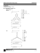
5. If there is a flow of liquid inside the tank, support the
cable where appropriate. (See Fig. 1)
6. Install piping so that air will not be entrapped. If piping
must be installed in such a way that air pockets are
unavoidable, install an air release valve wherever
such air pockets are most likely to develop.
7. Do not permit end of discharge piping to be sub
merged, as backflow will result when the pump is
shut down.
8. These pumps do not have an automatic operating
system based on built-in floats. Do not operate the
pump for a long time with the water level near the
minimum operating level as the automatic cut-off
switch incorporated inside the motor will be activated.
To avoid dry operation, install an automatic operating
system, as shown in Fig. 2 and maintain a safe
operating water level.
Before installation check rotation. Correct rotation is clockwise when viewed from top of motor. Read
ELECTRICAL WIRING.
Keep hands completely away from grinder impeller when making this check.
H
1
: Operating water level
This must be above the top of the motor.
H
2
: Lowest water level (motor flange)
Warning
CAUTION
!
!