
Assembly Instruction

IntegratedLED25WLightSource:
ToolsRequired:Flatheadscrewdriver, Phillips screwdriver,pliers,wirecutters,wirestrippers,electricaltape,safetyglasses,ladder, drill with
7/32-inchdrillbit.
EstimatedAssemblyTime:
Preparation:
45-60minutes
Identifyandinspectallpartsbeforebeginninginstallation.Checkpackagecontentlistanddiagramsbelowtobesureallpartsare
present.Ifanypartsaremissingordamaged,donotattempttoassemble,install,oroperatethefixture.Contactcustomerserviceforreplacement
parts.
1of3
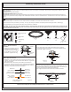
Package Contents
Warnings and Cautions
Turn off electricity at circuit breaker or main fuse box before installation. Consult a licensed electrician if in doubt.
These instructions are provided for your safety. It is very important you read them completely before installing the fixture. We strongly
recommend that a licensed, professional electrician perform the installation.
CAUTION: To reduce the risk of fire, electrical shock, or personal injury, do not touch or remove the spot light on the rail when the light
is on. Instead, turn off the electrical power. Unscrew the caps and to remove the spot light from the rail. Then reinstall them back onto
the desired positions of the rail.
C
Wall Anchor
x5
Self-tapping
Screw
x5
E
Spot Light
x5
Rail
x1
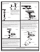
STEP 1 Attach Crossbar to
Outlet Box
-
A. Attach the Crossbar (A) to Outlet
Box and secure by threading
Outlet Box Screws (not supplied)
into the Mounting Holes on the
Outlet Box. Tighten until snug.
A
Figure 1
Outlet
Box
Outlet Box
Screw
B
Mounting Screw
x2
D
A
Crossbar
x1
F
Ceiling
Canopy
x1
G
Rail
Support
x5
H
STEP 3 - Attach Ceiling Canopy to Crossbar
A. Line up the holes on the side of the Ceiling Canopy (F) to the
mounting holes on the Crossbar (A). Secure them with Mounting
Screws (B). Tighten until sung.
A
B
F
Figure 3
STEP 4 Determine Support Position-
A. Identify the first Rail Supports (G) position approximately 14-18”
from the Ceiling Canopy (F) and mark the position.
B. By using the drill with 7/32-inch drill bit, drill holes on marks.
Therailmaybe
bent in gentle curves or straight line as desired.
Figure 4
Support Base
CEILING
G
F
14~18 inches
STEP 2 - Wire Connections
A. Wrap bare or green ground wire around green ground screw on the
crossbar, no less than 2 inches from the end of the wire. Tighten the
green ground screw.
B. Use standard wire connectors (not included) to make all wire
connections. Twist connectors until wires are tightly joined together.
Wrap each connection with approved electrical tape and carefully
stuff all the connected wires into the Outlet Box.
Figure 2
Green Ground Screw
on the Crossbar
White wire
from outlet box
White wire
from fixture
Black wire from
outlet box (or Red)
Black wire
from fixture
Bare, or Green
Ground wire
from outlet box
Ground wire
from Fixture
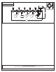
Assembly Instruction Sheet
Thank you forpurchasing product.
Need assistance withparts or assembly?Call customer service or visit us on-line