
Manual


8
D
S
GB
F
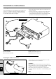
Please note!
The
CALLTRONIC
must be connected in accord-
ance with the circuit diagrams at the end of these
instructions. Note the type of heater!
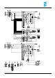
Circuit diagrams parts list
2.5.4 Switch on relay
2.5.9 Ventilation relay
3.1.11 Round operating device
3.1.17
AIRTRONIC
mini controller
3.1.18
CALLTRONIC
push-button
3.2.12 Time switch mini 12 / 24 volts
3.2.14 Time switch mini lighting (only 12 volts)
3.3.8
CALLTRONIC
remote control
3.8.3 Antenna
a) Connecting the operating elements to the heater
• rt Plus supply, terminal 30
• ge Contact signal S+
• gr Actual temperature value
• ws rt Switch off theft warning system
• br Minus supply, terminal 31
• bl ws; bl Diagnosis
• gr rt Set temperature value
• br ws Sensor reference signal
• sw ws Switch on ventilation
z) Terminal 58 (lighting)
Insulate any cable ends not used.
The connectors and socket housing are shown from
the cable entry side.
Cable colours
sw = black
ws = white
rt = red
ge = yellow
gn = green
vi = violet
br = brown
gr = grey
bl = blue
li = lilac