
Technical data

32
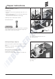
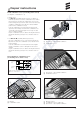
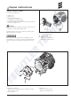
Repair step 5
Dismantle combination sensor (overheating / flame sen-
sor) (seeFigure5)
• Repairstep2.
• Removebothconnectorsfromthe“combinationsensor”
cableloomatthecontrolbox.
• Unlockbracketfromcombinationsensor.
• Removethecombinationsensor.
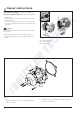
Figure5
“Combinationsensor”cableloom
Bracket,unlocked
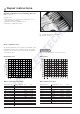
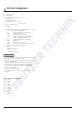
Check combination sensor
Theexternaltemperaturesensormustbecheckedwithadig-
italmultimeter.Replacetheoverheatingorflamesensorifthe
resistancevalueisnotthesameasthecurveinthediagram
orthetableofvalues.
Table of overheating sensor values
Temperature °C Resistance k min. max.
– 40 1597.00 1913.00
– 20 458.80 533.40
0 154.70 175.50
20 59.30 65.84
40 25.02 28.04
60 11.56 13.16
80 5.782 6.678
100 3.095 3.623
120 1.757 2.081
140 1.050 1.256
160 0.6554 0.792
180 0.4253 0.5187
200 0.2857 0.3513
Table of flame sensor values
Temperature °C Resistance min. max.
– 40 842.7 825.9 859.6
– 20 921.6 803.2 940.0
0 1000.0 980.0 1020.0
20 1077.9 1056.4 1099.5
40 1155.4 1132.3 1178.5
60 1232.4 1207.8 1257.1
80 1308.9 1282.8 1335.1
100 1385.1 1357.4 1412.8
120 1460.7 1431.5 1489.9
140 1535.8 1505.1 1566.6
160 1610.5 1578.3 1642.8
Resistance(kOhm)
Temperature(°C)
5
Notethemax.temperatureof320°Cforthetest.
Temperature(°C)
Resistance(Ohm)
Overheating sensor Flame sensor
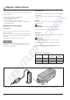
Repairinstructions
Please note!