IR Link Pro Flush IR Link Series – Extend your remote! IR Link Pro Flush – Mains Powered IR Remote Control Extender User guide 3 Bedienungsanleitung 8 Gebruiksaanwijzing 13 Användarmanual 18 Guide utilisateur 23 Guía del usuario 28 Manual do utilizador 33 Manuale per l’utente 38
Contents of the kit / Lieferumfang / Inhoud van de kit / Innehåll / Contenu du kit / Contenido del paquete / Conteúdo do kit / Dotazione del kit 1x IRLPRO IR Link Pro Flush Mount Receiver, including 4 interchangeable coloured top covers, 1x IRHUB4 Connecting Hub + Status input Jumper Cable, 2x 3IREDB Triple Blinking Emitter, including replacement adhesives 1x IRQC Quick Connect cable 1x 230V~50Hz to 12VDC 200mA Power Supply Adapter.
User Guide CONTENTS 1. Conformity of Use 2. Introduction 3. Kit content 4. How does the ebode IR Link Pro Flush work? 5. Installing the ebode IR Link Pro Flush 6. Operation 7. How to avoid and solve possible problems 8. Technical information 1. Conformity of Use For carefree and safe use of this product, please read this manual and safety information carefully and follow the instructions. The unit is registered as a device that does not cause or suffer from radio-frequency interference.
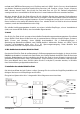
This kit contains two 3IREDB Triple Blinking Emitters for control of 6 devices, and a 1IRQC Quick Connect cable for direct control of popular Audio/Video Receivers (e.g. Yamaha, Onkyo, Denon, Marantz, NAD, Harman Kardon, Pioneer, Sony etc). The IR Link Pro Flush Kit runs on a 12VDC mains adapter (included) and is expandable with extra IR Link Receivers in different rooms.
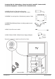
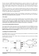
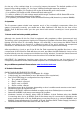
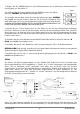
1. Attach the 3IREDB Emitters onto the IR Sensor Windows of the components in your system that you wish to control. Refer to Fig. 2. 2a. Plug the yellow mini plugs of the 3IREDB into one of the yellow labelled "EMITTERS" jacks of the IRHUB4 Connecting Hub. Fig 2 2b. Plug the IRQC cable into one of the yellow labelled “EMITTERS” jacks of the IRHUB4, and the other side into the 3.5 mm mono IR input of your AVR. IRED Mono TS 3.5mm pin configuration: tip is IR Data, sleeve is Ground.
On the top of the cabinet there is a cut out for jumper placement. The default position of the jumper is the parking position JP1.
NOTE: Unit will not work with certain brands & models that operate at higher frequencies (e.g. B&O). Contact ebode Technical Support for more information. Cable requirements for long lengths to remote rooms: 3-conductor, 24AWG/0,2mm2 solid or stranded wire up to 50m, 22AWG/0,35mm2 up to 100m, 20AWG/0,5mm2 up to 200m and 18AWG/1mm2 up to 300m (unshielded OK).
Bedienungsanleitung INHALT 1. Betriebsanleitung 2. Einführung 3. Inhalt 4. Wie funktioniert der ebode IR Link Pro Flush? 5. Installation des ebode IR Link Pro Flush 6. Gebrauch 7. Problemlösungen 8. Technische Informationen 1. Konformaitätserklärung Bitte lesen Sie diese Bedienungsanleitung und Sicherheitsinformationen für eine sorgenfreie und sichere Anwendung dieses Produktes. Das Gerät ist als Apparat registriert, welches keine RadioFunkfrequenzen stört und auch von diesen nicht gestört wird.
umfasst zwei 3IREDB zur Steuerung von 6 Geräten sowie ein 1IRQC Quick Connect Anschlusskabel zur direkten Steuerung populärer Audio/Video Receiver (z.B. Yamaha, Onkyo, Denon, Marantz, NAD, Harman Kardon usw.). Der IR Link Pro Flush wird über ein 12 V DC Netzteil (mitgeliefert) versorgt und kann um zusätzliche IR Link Receiver in verschiedenen Räumen erweitert werden. Mit dem ebode IR Link Pro Flush können Sie die InfraRot Signale Ihrer eigenen Fernbedienung verlängern.
1. Bringen Sie die 3IREDB Emitter an den IR-Sensorfenstern der zu steuernden Komponenten in Ihrem System an. Siehe Abb. 2. Abb 2 2a. Schließen Sie die gelben Ministecker des 3IREDB an einer der gelben Buchsen „EMITTERS“ des IRHUB4 Anschlussblocks an. 2b. Schließen Sie das IRQC-Kabel an einer der gelben Buchsen „EMITTERS“ des IRHUB4 an und die andere Seite am 3,5 mm Mono IR-Eingang Ihres AVR.
Steckbrückenpositionen: - Standard, Steckbrücke (JP) auf Position JP1: Feedback-LED aktiv & Status-LED nicht aktiv/wird nicht verwendet - Steckbrücke auf Position JP2: Sowohl Feedback-LED als auch Status-LED immer AUS - Überbrückungskabel auf JP2 mit Spannungsversorgung innerhalb des Bereichs: Feedback-LED & Status-LED aktiv (je nachdem, ob externe Spannung vorhanden) - Steckbrücke auf Position JP3: Feedback-LED aktiv & Status-LED immer AN (abhängig von Stromversorgung zum IRHUB4) 6.
• • Höchstzahl direkt betriebener IRED IR-Emitter: 4 Dreifach-Emitter mit IRHUB4 Anschlussbock. Bis zu sechs IRLPRO Flush IR-Receiver können parallel an den Schraubanschlusseingängen des IR Link IR HUB Serie Anschlussblocks (z.B. optionales IRHUB2CI und IRHUB4) angeschlossen werden. Spannungsanforderungen: 12 Volt DC bei 25 mA. Benötigt 12 V DC Spannungsversorgung (mitgeliefert).
Gebruiksaanwijzing INHOUD 1. Gebruiksvoorschrift 2. Introductie 3. Inhoud 4. Hoe werkt de ebode IR Link Pro Flush? 5. Werkt de ebode IR Link Pro Flush altijd? 6. Installeren van de ebode IR Link Pro Flush 7. Gebruik 8. Wat te doen bij problemen 9. Technische informatie 1. Gebruiksvoorschrift Lees voor een zorgeloos en veilig gebruik van dit product deze handleiding en de veiligheidsinformatie zorgvuldig door en volg deze op.
De IR Link Pro Flush werkt met een 12VDC voedingsadapter (inbegrepen) en is uit te breiden met extra IR Link Ontvangers in verschillende kamers. Met de ebode IR Link Pro Flush kunt u de InfraRood signalen van uw eigen afstandsbediening verlengen. ebode IR Link Pro Flush maakt het mogelijk om uw A/V apparatuur te bedienen terwijl deze in een gesloten kast of andere ruimte staat of verdekt is opgesteld. De ebode IR Link Pro Flush maakt gebruik van een voedingsadapter en u hebt dus geen batterijen nodig.
1. Bevestig de 3IREDB Emitters op het IR sensorraampje van de componenten in uw systeem die u wilt bedienen. Zie Fig. 2. Fig 2 2a. Steek de gele ministekkers van de 3IREDB in één van de gele "EMITTERS" uitgangen van het IRHUB4 verdeelblokje. 2b. Steek de IRQC kabel in één van de gele ingangen gemarkeerd “EMITTERS” van de IRHUB4, en het andere uiteinde in de 3,5 mm mono IR ingang van uw AVR. IRED Mono TS 3,5mm stekkerconfiguratie: tip is IR Data, mantel is Massa GND.
De bovenkant van de IRHUB4 is voorzien van een uitsparing waar jumpers geplaatst kunnen worden. De standaard instelling is jumper positie 1 (JP1). Door de jumper te verplaatsen zijn er 3 verschillende mogelijkheden voor het gebruik van de Status LED in de IR Ontvanger: - Standaard, jumper in positie JP1: Feedback LED is actief, en Status LED niet actief cq ongebruikt - Jumper verplaatsen naar JP2: Feedback LED alsook Status LED zijn beiden uitgeschakeld.
• • • • Feedback LED (BLAUW). Geeft alleen InfraRood ontvangst aan wanneer Emitter(s) zijn verbonden. Status LED (AMBER). Geeft de voedingsstatus aan van het A/V systeem Maximaal aantal direct aangedreven IRED IR Emitters: 4 drievoudige Emitters gebruikmakend van het IRHUB4 verdeelblok. Tot op zes IRLPRO Flush IR Ontvangers kunnen parallel aangesloten worden op de schroefklemingangen van de IR Link IRHUB serie verdeelblokken (bijv. optionele IRHUB2CI en IRHUB4). Stroomvereisten: 12 volts DC @ 25 mA.
Användarmanual INNEHÅLL 1. För bästa användning 2. Introduktion 3. Innehåll 4. Hur fungerar ebode IR Link Pro Flush? 5. Finns det förhållanden då ebode IR Link Pro Flush inte fungerar? 6. Installera ebode IR Link Pro Flush 7. Användning 8. Problemlösning 9. Specifikationer 1.
2. Introduktion Gratulerar till ditt val att köpa ebode IR Link Pro Flush. Vår eIR2xTM -teknik (uttalas Irex) ger en hög nivå av immunitet mot InfraRöda störningar genom direkt solljus, CFL-belysning och platt-TVapparater (inklusive Plasma, LCD och LED). Satsen innehåller två 3IREDB för styrning av 6 enheter och en 1IRQC snabbanslutningskabel för direktkontroll av vanliga audio/videomottagare (t.ex. Yamaha, Onkyo, Denon, Marantz, NAD, Harman Kardon etc).
1. Fäst de 3IREDB-sändarna på IR-sensorfönstren på de komponenter i ditt system som du vill styra. Se Fig 2. Fig 2 2a. Anslut de gula minikontakterna från 3IREDB till någon av de gula "EMITTERS"-uttagen på IRHUB4 anslutningsmodul. 2b. Anslut IRQC-kabeln till någon av de gula “EMITTERS”-uttagen på IRHUB4 och den andra änden i 3,5 mm monoingång på din AVR. IRED Mono TS 3,5mm stiftskonfiguration: spets är IR-data, mantel är Jord. (KONTROLLERA I MANUALEN FÖR ENHETEN FÖR PASSANDE STIFTSKONFIGURATION) 3.
Ovanpå skåpet finns en brytkontaktor för bygelplacering.Standardinställningen för bygeln är i parkerad position JP1.
OBS: Enheten fungerar inte med vissa märken och modeller som drivs vid högre frekvenser (t.ex. B&O). Kontakta ebode Tekniska support för mer information. Kabelspecifikationer för längre kabel till angränsande rum: 3-ledare, 24AWG/0,2 mm 2 solid eller platt kabel upp till 50 m, 22AWG/0,35 mm2 upp till 100 m, 20AWG/0,5 mm2 upp till 200 m och 18AWG/1 mm2 upp till 300 m (oskyddad OK).
Guide utilisateur TABLE DES MATIERES 1. Utilisation 2. Introduction 3. Contenu du kit 4. Comment fonctionne l’IR Link Pro Flush ebode? 5. Y-a-t-il des conditions où l’IR Link Pro Flush ebode ne fonctionnera pas ? 6. Installation du l’IR Link Pro Flush ebode 7. Fonctionnement 8. Comment faire pour éviter et résoudre les problèmes éventuels ? 9. Informations techniques 1. Utilisation: Pour une utilisation correcte et sans danger de ce produit, veuillez lire attentivement ce manuel et suivre ses instructions.
audio/vidéo connus (par exemple, Yamaha, Onkyo, Denon, Marantz, NAD, Harman Kardon, etc.). IR Link Pro Flush fonctionne sur un adaptateur secteur 12VCC (fourni) et est extensible avec des récepteurs supplémentaires IR Link dans les différentes pièces. Le IR Link Pro Flush ebode est un système d’extension InfraRouge qui permet de contrôler à distance des équipements A/V situés derrière un placard fermé, cachés, une autre chambre, ou tout simplement hors de portée.
1. Fixez les émetteurs 3IREDB au dessus du capteur IR des composants de votre système que vous souhaitez contrôler. Reportez-vous aux Fig. 2. Fig 2 2a. Branchez les minis prises jaunes du 3IREDB dans l'une des prises jaunes "EMITTERS" du connecteur de blocs IRHUB4. 2b. Branchez le câble IRQC dans l'une des prises jaunes "EMITTERS" du IRHUB4, et l'autre extrémité à l'entrée IR mono 3,5 mm de votre AVR. Configuration des broches InfraRouges mono 3,5 mm TS : Pointe = données IR, Manchon = Masse.
- Défaut, JP en position JP1 : DEL de rétroaction active & DEL d’état non active/inutilisé - JP en position JP2 : DEL de rétroaction & DEL d’état toutes les deux éteintes - Câble JP en position JP2 avec alimentation en tension dans la fourchette : DEL de rétroaction & DEL d’état actives (à condition qu’il y ait une tension externe présente) - JP en position JP3 : DEL de rétroaction active & DEL d’état toujours allumée (si IRHUB4 est alimenté) 6.
• • Nombre maximum d'émetteurs InfraRouges directement contrôlés : 4 émetteurs triple utilisant le concentrateur de connexion IRHUB4. Jusqu'à six récepteurs IR IRLPRO Flush peuvent être connectés en parallèle aux bornes d'entrée à vis du lien infrarouge en série du connecteur de blocs IRHUB (par exemple IRHUB2CI et IRHUB4 en option). Exigences d'alimentation : 12 volts CC @ 25 mA. Nécessite une alimentation de 12VCC (fournie).
Guía del usuario CONTENIDOS 1. Condiciones de uso 2. Introducción 3. Contenidos 4. ¿Cómo funciona el ebode IR Link Pro Flush? 5. ¿Existen condiciones en las que el ebode IR Link Pro Flush no funcione? 6. Instalación de la ebode IR Link Pro Flush 7. Funcionamiento 8. Cómo evitar y resolver posibles problemas 9. Información técnica 1. Condiciones de uso Para un uso sin problemas y seguro de este producto lea cuidadosamente este manual y la información de seguridad, y siga las instrucciones.
conjunto contiene dos 3IREDB para el control de 6 dispositivos, y 1 cable de Conexión Rápida 1IRQC para control directo de los Receptores de audio/vídeo más populares (p.ej. Yamaha, Onkyo, Denon, Marantz, NAD, Harman Kardon etc). El IR Link Pro Flush funciona con un adaptador eléctrico de 12VCC (incluido) y se puede extender su capacidad a otras habitaciones con Receptores IR Link adicionales.
1. Fije los Emisores 3IREDB sobre las Ventanas de los Sensores IR de los componentes de su sistema que desee controlar. Vea las Figs. 2. Fig 2 2a. Conecte la mini-clavija amarilla del 3IREDB en uno de los conectores "EMITTERS" amarillos del Bloque de Conexiones IRHUB4. 2b. Conecte el cable IRQC en uno de los conectores amarillos con la etiqueta “EMITTERS” del IRHUB4, y el otro extremo en la entrada IR mono de 3,5 mm de su AVR.
En la parte superior del gabinete existe un orificio para colocar el puente. La posición predeterminada del puente es la posición de estacionamiento JP1.
• • • • LED de Estado (ÁMBAR). Indica si el sistema A/V está encendido. Número máximo de Emisores IR IRED gobernados directamente: 4 Emisores triples usando el Concentrador de Conexiones IRHUB4. Hasta seis Receptores IR IRLPRO Flush se pueden conectar en paralelo en la entrada de terminales de tornillo de los Bloques de Conexiones de la serie IR Link IRHUB (p.ej. opcional en IRHUB2CI y IRHUB4). Requisitos de alimentación eléctrica: 12 voltios CC @ 25 mA.
Manual do utilizador CONTEUDO 1. Conformidade de utilizaçäo 2. Introdução 3. A embalagem contém 4. Como é que o ebode IR Link Pro Flush funciona? 5. Existem algumas condições nas quais o ebode IR Link Pro Flush não funciona? 6. Instalar o ebode IR Link Pro Flush 7. Operação 8. Como evitar e resolver problemas 9. Informação técnica 1. Conformidade de utilizaçäo Para uma utilização segura deste equipamento, por favor leia este manual e siga as instruções de instalação.
provenientes da luz solar directa, iluminação CFL (lâmpadas fluorescentes) e aparelhos de TV de ecrã plano (incluindo plasma, LCD e LED). Este conjunto inclui dois 3IREDB para controlo de 6 dispositivos, e um cabo IRQC Quick Connect para controlo directo dos Receptores normais de áudio/vídeo (por ex. Yamaha, Onkyo, Denon, Marantz, NAD, Harman Kardon, etc.) O IR Link Pro Flush funciona com um transformador de 12VDC (incluído) e é expansível com Receptores IR Link extra em espaços diferentes.
1. Faça a conexão dos Emissores 3IREDB na janela do Sensor IR, dos componentes do sistema que pretende controlar. Consultar as Fig. 2. Fig 2 2a. Ligue a mini ficha amarela do 3IRED8 numa das tomadas amarelas dos "EMISSORES" do Bloco de Ligações IRHUB4. 2b. Ligue o cabo IRQC numa das tomadas etiquetadas a amarelo dos "EMISSORES" do IRHUB4, e o outro extremo na entrada mono IR 3.5mm do seu AVR. Configuração do pino IRED Mono TS 3.5mm: ponta é IR Data, acoplamento é Ground (Terra).
- Predefinida, JP na posição JP1: O LED de feedback activo & LED de Estado inactivo/não utilizado - JP na posição JP2: Tanto o LED de Feedback como o de Estado LED devem estar sempre DESLIGADOS (OFF) - Cabo JP na posição JP2 com tensão de alimentação dentro da gama: LED de feedback & LED de Estado activo (dependendo da tensão externa presente) - JP na posição JP3: Tanto o LED de Feedback activo como o de Estado LED devem estar sempre LIGADOS (ON) (baseado em corrente para IRHUB4) 6.
• • • LED Estado (ÂMBAR): Indica estado de alimentação do sistema A/V. Número máximo de Emissores IRED IR dirigidos directamente: 4 Emissores triplos usando o Controlador de Ligação IRHUB4. Podem ser ligados em paralelo até 6 IR Receptores IRLPRO Flush na entrada dos terminais de parafuso das séries IR Link, IRHUB que estão a ligar blocos (por ex. IRHUB2CI e IRHUB4 opcionais). Requisitos de alimentação: 12 volts DC @ 25 mA. Requer um transformador de 12VDC (incluído).
Manuale per l’utente INDICE 1. Conformità d’uso 2 . Introduzione 3. Contenuto della confezione 4. Come funziona ebode IR Link Pro Flush? 5. Esistono condizioni di non funzionamento di ebode IR Link Pro Flush? 6. Installazione di ebode IR Link Pro Flush 7. Funzionamento 8. Come evitare e risolvere eventuali problemi 9. Informazioni tecniche 1.
LCD e LED). Questo kit contiene due 3IREDB per il controllo di 6 dispositivi, e un cavo di Collegamento Rapido 1IRQC per il controllo diretto dei ricevitori audio / video più popolari (ad esempio Yamaha, Onkyo, Denon, Marantz, NAD, Harman Kardon, ecc). L'IR Link Pro Flush funziona con un alimentatore da 12VDC (incluso) ed è espandibile con Ricevitori IR Link extra in stanze diverse.
1. Fissare gli Emettitori 3IREDB sulla Finestra del Sensore IR dei componenti nel sistema che si desidera controllare. Fare riferimento alle Fig. 2. Fig 2 2a. Inserire le mini spine gialle del 3IREDB in una delle spine jack gialle "EMETTITORI" del Blocco di Collegamento IRHUB4. 2b. Collegare il cavo IRQC in una delle prese jack gialle con l'etichetta "EMETTITORI" del IRHUB4, e l'altra estremità nell'ingresso IR mono da 3,5 mm del vostro AVR.
Nella parte superiore dell’armadio c'è un intaglio per l'installazione del cavo jumper. La posizione predefinita del jumper è la posizione JP1 di parcheggio.
• • • LED di Stato (AMBRA). Indica lo stato di alimentazione del sistema A / V Numero massimo di Emettitori IR IRED ad azionamento diretto: 4 Emettitori tripli utilizzando l'Hub di Collegamento IRHUB4 . Fino a sei ricevitori IR IRLPRO Flush possono essere collegati in parallelo all'ingresso dei morsetti a vite dei blocchi di collegamento serie IR Link IRHUB (ad esempio, opzionale IRHUB2CI e IRHUB4). Requisiti di alimentazione: 12 volt DC a 25 mA. Richiede Alimentatore da 12VDC (incluso).
DECLARATION OF CONFORMITY Hereby, ebode electronics, declares that this ebode IR Link Pro Flush is in compliance with the essential requirements and other relevant provisions of the following Directives: Directive 2004/108/EC of the European Parliament and of the Council of 15 December 2004 on the approximation of the laws of the Member States relating to electromagnetic compatibility Directive 2006/95/EC of the European Parliament and of the Council of 12 December 2006 on the harmonization of the laws of M
www.ebodeelectronics.