
User guide


20-11-2009 10 033000=14888C
In case of improper usage or if you have opened, altered and repaired the product yourself,
all guarantees expire. The supplier does not accept responsibility in the case of improper
usage of the product or when the product is used for purposes other than specified. The
supplier does not accept responsibility for additional damage other than covered by the
legal product responsibility.
2. INTRODUCTION
The VideoLink ADVANCED enables you to transmit a video signal from your VCR, Satellite
receiver, Cable box, DVD-player, DVD-recorder, Satellite receiver, set top box, PC etc. to a
(second) TV without running wires. The transmitter sends an Audio/Video signal from 2
different sources to the receiver via 5.8GHz radio frequency signals. The receiver converts the
radio signal back into an A/V signal. The receiver also converts the infrared signals sent by
the remote control of the A/V source into radio frequency signals. The transmitter will then
reconvert these signals into infrared signals in order to control the connected A/V devices.
Using the 5,8GHz frequency, you will normally have no problems with distortion from wireless
(WiFi) networks, Cordless phones and microwave for example.
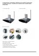
3. SET CONTENTS.
1 Transmitter 1 RCA cable (white / red / yellow)
1 Receiver 2 SCART adapters (labelled Transmitter).
2 Power Supply adapters 1 SCART adapter (labelled Receiver)
1 IR Extender cable with 3 LEDs. 1 SCART adapter (labelled AV OUT).
1 3,5 mm jackplug / RCA adapter (audio) 1 UHF Coaxial cable
3 Mini-DIN / RCA cables (white / red / yellow). 1 User manual
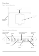
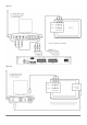
4. LEGEND:
(Pictures on page 4-6)
Transmitter Receiver
Mini DIN input ‘AV IN 1’ Mini DIN output AV EXTEND
Mini DIN input ‘AV IN 2’ UHF/RF Coaxial output
DC input 7,2V 320 mA DC input 7,2V 250mA
Mini DIN output AV OUT Audio/Video receiver aerial
Source selection Switch ½ (LOCAL SELECTOR) IR transmitter antenna
Output for infrared extender IR EXT. Operating LED / infrared receiver
Audio/Video transmitter aerial Source selection Switch ½
IR transmitter antenna ON/OFF switch
Operating LED Channel switch A/B/C/D
On/OFF switch
Channel switch A/B/C/D
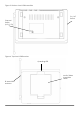
5. SETTING UP THE TRANSMITTER
See figure 7 on page 7.
The transmitter can be connected to two A/V devices and a local television set.
1. Connect the RCA/RCA cable to the ‘A/V IN 1’ or the Mini-DIN/RCA cable on the ‘A/V IN 2’
of the transmitter.