D2112-KJX01 User Manual Date: July 27, 2020
catalogue 目录 catalogue ................................................................................................................................................................................................. 2 1. Moudle Parameters ............................................................................... 3 2. Pins and definitions ...................................... 4 3. Block Diagram ............................................. 5 Bluetooth Radio ...........................................
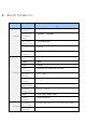
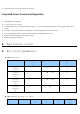
1. Moudle Parameters category wireless Hardware Software parameter expl ain Bluetooth version BT5.0 Operating frequency band 2402MHz ~ 2480MHz Receiving sensitivity -The95dBm@1M authenticatio n FCC/CE Appearance dimension (24.8±0.2)mm x (16±0.2)mm x (3.5±0.2)mm Bluetooth chip FR8016H SRAM 48KB Flash 512KB data interface UART/SPI/I2C/PWM/ADC/I2S/PDM working voltage 1.8V ~ 4.
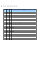
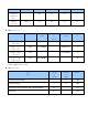
2. Pins and definitions Pin definition Foot posi tion name type desc ribe 1 GND GND 2 Pa5 Dio Data_UART_TX 3 PA4 Dio Data_UART_RX 4 PA6 Dio At_Mode 5 PA7 Dio Wakeup 6 PA0 Dio GPIO 7 NC / 8 PA3 Dio HCI_UART_TX (burning port) 9 Pa2 Dio HCI_UART_RX (burning port) 10 VBAT AI Positive supply input (1.8~4.
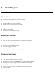
3. Block Diagram Bluetooth Radio On-chip balun (50Ω impedance in TX and RX modes) No external trimming is required in production Qualified to Bluetooth v5.
Watchdog used for tracking unexpected exception Integrated Power Control and Regulation Embedded Power-On-Reset Low power 0.9v core voltage On-chip high efficiency switch-mode power supply, 1.8v to 4.
value value value working temperat ure - -40 25 65 ℃ Supply voltage VCC 1.8 3.3 4.3 V Digital port category name minimum value Typica l value Maximum value Compan y Input logic low level Vil -0.3 - 0.3*VDDIO V Input logic high level VIH 0.7*VDDIO - VDDIO+0.3 V Output logic low level Vol - - 0.1*VDDIO V Output logic high level Voh 0.
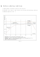
6. Reflow soldering conditions 1. 1.Heating method: conventional convection or IR convection; 2. 2.Allowable reflow times: 2 times, based on the following inclined heating conditions; 3. 3.Maximum temperature: 250 ° C.
7. Electrostatic discharge warning Modules will be damaged due to electrostatic discharge. It is recommended that all modules should be handled under the following three preventive measures: 1Anti static measures must be followed, and the module cannot be held with bare hands. 2The module must be placed in a placement area that can prevent static electricity. 3The antistatic circuit at the high-voltage input or high-frequency input should be considered in the product design.
FCC Caution: Any Changes or modifications not expressly approved by the party responsible for compliance could void the user's authority to operate the equipment. This device complies with part 15 of the FCC Rules. Operation is subject to the following two conditions: (1) This device may not cause harmful interference, and (2) this device must accept any interference received, including interference that may cause undesired operation. FCC RF Radiation Exposure Statement: 1.