
Warranty

27
PLEASE NOTE: 20H IS FOR OUTDOOR PERMANENT INSTALLATIONS ONLY AND 20HI IS FOR INDOOR PERMANENT INSTALLATIONS ONLY. THIS MANUAL
AND ALL ECCOTEMP CONTENT IS SUBJECT TO CHANGE WITHOUT NOTICE. PLEASE VISIT WWW.ECCOTEMP.COM/SUPPORT FOR MORE INFORMATION.
Support: Eccotemp.com/help-desk Shop Online: Eccotemp.com/products Store Locator: Eccotemp.com/locator
Phone: 866-356-1992 | Email: Support@eccotemp.com | Address: 315 - A Industrial RD Summerville, SC 29483
English
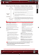
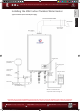
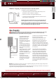
Pressure
Relief Valve
Discharge Line
(To Suitable Drain)
Hot
Water
Supply
Outlet
Cold Water
Supply Line
Shut-o Valve
Manual Gas
Appliance
Shut-O
(Suplied)
WARNING:
Never use an open ame
to test for gas leaks as
property damage, personal
injury, or death could
result.
The water heater and its gas connections must be leak tested at normal operating
pressures before it is placed in operation.
• Turn on the gas shut-o valve(s) to the water heater.
• Use a commercial leak detector or soapy water solution to test for leaks at all
connections and ttings. Bubbles indicate a gas leak that must be corrected.
All connections should also be leak tested after the water heater is placed in
operation.
Pressure Testing the Gas Supply System
WARNING: Install a gas pressure regulator, in the gas supply line, which does not exceed the maximum
supply pressure. DO NOT use an industrial type gas regulator.
The water heater must be isolated from the gas piping system by closing the manual gas shut-o valve during any
pressure testing of the gas supply piping at pressures equal to or less than 1/2 psi (14’w.c.) .
High Altitude
The Eccotemp 20H and 20HI Gas Tankless Water Heaters have been tested for use at elevations up to 2,000 feet.
Installation and use of the Eccotemp 20H and 20HI Gas Tankless Water Heaters above 2,000 feet may eect overall
product eciency and performance. Installation and use of the Eccotemp 20H and 20HI Gas Tankless Water Heaters
above 5,000 feet is not recommended.
Leak Testing
A new pressure relief valve, complying with the Standard for relief Valves and Automatic Gas Shut-O
Devices for Hot Water Supply Systems, ANSI Z21.22, must be installed at the hot water outlet connection of
the water heater at the time of installation. Local codes shall govern the installation of relief valves.
For safe operation of the water heater, be sure that:
• The pressure rating of the relief valve must not exceed 150 psi, the maximum working pressure of the water
heater as marked on the rating plate.
• The BTUH rating of the relief valve must equal or exceed the BTUH input of the water heater as marked on its
rating plate.
• No valve of any type should be installed between the relief valve and the water heater.
• Discharge from the relief valve should be piped to a suitable drain to eliminate potential water damage. Piping
used should be of a type approved for the distribution of hot water.
• Hot and cold water lines should be insulated up to the water heater.
• The discharge line must be NO SMALLER than the outlet of the valve and must pitch downward to allow
complete drainage (by gravity) of the relief valve and discharge line.
• The end of the discharge line should not be threaded or concealed and should be protected from freezing. No
valve of any type, restriction or reducer coupling should be installed in discharge line.
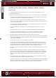
NOTICE: The diagram below illustrates a pressure only relief valve. If local codes require a combination
temperature and pressure relief valve be installed, an extension piece may be needed.
Relief Valve
NOTICE: Local codes govern the installation of relief valves. If local codes
require that a temperature and pressure relief valve should be installed
the manufacturer recommends a type 40XL Watts T&P relief valve or an
equivalent model be used.
NOTICE: Manual operation of relief valves should be performed at least
once a year. Turn o the electrical power and gas shuto valve. Lift and
release lever on the relief valve and check the manual operation of the
relief valve. You should take precaution to avoid contact with the hot
water coming out of the relief valve and to prevent water damage.
NOTICE: If the relief valve on the system discharges periodically, this
may be due to thermal expansion in a closed water supply system.
Contact the water supplier or local plumbing inspector on how to correct
this situation. Do not plug the relief valve.
20HI Installation
English-20Liter-Series-ManualV4_OK.indd 27 3/12/2019 10:55:03 PM