
Installation Guide


4
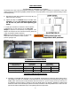
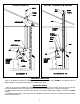
2. The system can now be assembled through the thimble (attach the termination first - note “UP” arrow) and then back to
the appliance as per illustration using JOINT PROCEDURE as described on page #3. A gear clamp (or locking band)
must be installed around the pipe on the inside of wall to trap pipe in position so that the system cannot be moved in or
out of wall (see images 4 & 5). This applies to both combustible and non-combustible walls
IMAGES 4 & 5
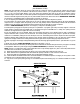
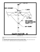
3. The system must be supported along its horizontal length at all elbow locations (see illustration 2 below) and joints (every
forty-eight inches or less) using straps around pipes maintaining clearance to combustibles as per table on page 3.
4. The horizontal distance of the system from the appliance flue collar to the outside of the horizontal termination cannot be
greater or less than that specified in the appliance manufacturer’s installation instructions. Any horizontally installed
portion of a venting system shall have a slope (upwards for Category II, III, or IV appliances or downwards for Category
III or IV appliances) not less than 1/4” (6.4 mm) every 12 inches (305 mm) to prevent collection of condensate at any
location in the assembly. Fasteners must not penetrate the components of the system either when joining
pipes and fittings or using support straps. Drilling holes in the vent components is not permitted.
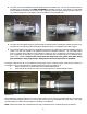
The lengths of pipe may be cut on non-expanded end using aviation snips or a hacksaw (24 tpi). Make certain to keep the cut
end cylindrical. The cut end must be filed or sanded smooth before joining (see images 6 & 7).
i) Measure 2 inches from cut end and draw a line to indicate depth insertion.
ii) Insert male end into female end to within ¼ inch of the drawn line to achieve full depth insertion.
IMAGES 6 & 7
When installing the condensate tube be sure to form a trap by means of a 3 inch (76.2 mm) loop filled with water. This tube must
be 3/8 inch ID high temperature silicone for at least the first 6 inches (152 mm) and attached with a gear clamp or hose clamp
(see image 8 & 9). The effluent must be disposed of according to local regulations.
NOTE: Z-FLEX recommends using a neutralizer kit when using a condensate trap. A condensate pump may be required.