
Installation Guide


6
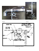
VERTICAL VENTING
(see illustrations #3 & 4)
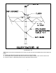
NOTE: The vent termination above the roof line shall consist of a continuous section of vent pipe only (without any joints) and
must be at least 3 ft. (1 m) to a maximum of 6ft. above the roof line and 2 ft. (.61 m) higher than any part of a structure within
10 ft. (3.1 m). The total vertical distance of the vent system from appliance flue collar to the rain cap termination and the
maximum length of offsets shall not exceed that specified in the appliance manufacturer’s installation instructions. No continuous
vertical run shall be longer than sixty feet (18.3 m). All horizontal sections must observe the rules for HORIZONTAL VENTING.
The clearance to combustibles inside a chase shall be no less than 4” (100 mm).
1. Prior to beginning the installation loosely assemble all parts required to make sure all parts are present.
2. Locate position for venting system and proceed to cut holes for firestop support and firestop spacers. All vertical installations
require the use of a support. Frame the opening of the floor using lumber, which is dimensionally consistent with the structural
members. Insert the support from beneath the framed opening and secure with nails or screws as required.
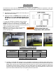
3. Refer to JOINT PROCEDURE (
illustration #1 & images 1, 2 &3
) before assembling system.
4. Install system joining pipe as required up through roof (
illustration
#3
). Tighten gear clamp on firestop support to hold vent
system. NOTE: A firestop must be provided when a vent passes through a combustible floor or ceiling. The opening must be
framed for the support since the support also serves as a firestop.
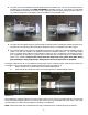
5. The roof flashing can now be installed. Where the vent passes through the roof a flashing must be used to maintain the
required clearances and to protect from the elements. The framed opening must be large enough to provide the necessary
clearances to combustibles, taking into account the slope of the roof. The flashing can be used on slopes from flat to 6/12 pitch.
Install the flashing while holding the pipe centered in the opening. Fasten the flashing to the roof under the roofing material
upslope from the pipe and above the roofing material below the pipe. Seal as required using high temperature silicone.
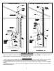
6. Install Top Support around pipe and against flashing collar and seal using high temperature silicone. (see i
llustration #3, 4, 5 &
6)
7. Attach rain cap using. JOINT PROCEDURE (
illustration #1 & images 1, 2, & 3
)
8. The vertical section is connected by an elbow joined to the horizontal run and then through a drain tee (
see page 9 for details
)
to the appliance. Elbows are joined to pipe using the JOINT PROCEDURE (see
illustration #1 & images 1, 2 & 3
).
NOTE: If there is no solid anchor point in the system below the roof (ie Firestop Support etc.) then a Z-Vent Guy Band must be
used below the roof as follows. (
see illustration #6)
a. Attach the Guy Band at any point above an elbow or tee in the vertical section within 20 feet of the roof.
b. Fasten stainless steel or galvanized cable with a minimum capacity of 500 lbs. to each of the four anchor holes.
c. Anchor the cables to a rigid building member using an appropriate fastening method.
9. A drain tee MUST be installed at the bottom of all vertical stacks in a conditioned space for a category IV vent system to collect
and dispose of any condensate that may occur in the vent system.
11. Any part of a vent system passing through an unconditioned space where freezing may occur shall be installed into a chase
enclosure.
ABOVE THE ROOF