FTXL User’s Guide ® 078-0363-01A
Echelon, LONWORKS, LONMARK, NodeBuilder, LonTalk, Neuron, 3120, 3150, LNS, i.LON, ShortStack, LonMaker, and the Echelon logo are trademarks of Echelon Corporation registered in the United States and other countries. 3190, FTXL, OpenLDV, Pyxos, and LonScanner are trademarks of Echelon Corporation. Other brand and product names are trademarks or registered trademarks of their respective holders.
Welcome Echelon’s FTXL™ products enable any product that contains an Altera® Nios® II processor to quickly and inexpensively become a networked smart device. An FTXL device includes a complete ANSI/CEA 709.1-B (EN14908.1) implementation that runs on the Nios II embedded processor. Thus, the FTXL 3190™ Free Topology Smart Transceiver Chip provides a simple way to add LONWORKS® networking to smart devices.
• Introduction to the LONWORKS System (078-0183-01A). This manual provides an introduction to the ANSI/CEA-709.1 (EN14908) Control Networking Protocol, and provides a high-level introduction to LONWORKS networks and the tools and components that are used for developing, installing, operating, and maintaining them. • LONMARK® Application Layer Interoperability Guidelines. This manual • FT 3120 / FT 3150 Smart Transceiver Data Book (005-0139-01D).
Product Category Documentation Titles Nios II processor Nios II Hardware Development Tutorial Nios II Software Development Tutorial (included in the online help for the Nios II EDS integrated development environment) Nios II Flash Programmer User Guide Nios II Processor Reference Handbook Nios II Software Developer's Handbook Cyclone® II and Cyclone III FPGA and device configuration Cyclone II Device Handbook Cyclone III Device Handbook Configuration Handbook USB-Blaster™ download cable USB-Blaster D
vi
Table of Contents Welcome .........................................................................................................iii Audience ........................................................................................................iii Related Documentation ................................................................................iii Related Altera Product Documentation ................................................ iv Related devboards.de Product Documentation.......................
Specifying the Authentication Key....................................................... 44 How Authentication Works................................................................... 45 Managing Memory ....................................................................................... 46 Address Table ........................................................................................ 47 Alias Table .............................................................................................
Initializing the FTXL Device ................................................................ 81 Periodically Calling the Event Pump................................................... 81 Sending a Network Variable Update ................................................... 83 Receiving a Network Variable Update from the Network .................. 85 Handling a Network Variable Poll Request from the Network.......... 88 Handling Changes to Changeable-Type Network Variables ..............
Keywords.............................................................................................. 132 The Network Variable Modifier ................................................... 132 The Network Variable Storage Class .......................................... 134 The Network Variable Type ......................................................... 134 The Network Variable Connection Information ......................... 135 The Network Variable Initializer...........................................
Managing Interrupts ........................................................................... 179 Determining Memory Usage for FTXL Applications .....................................181 Overview ..................................................................................................... 182 Total Memory Use ............................................................................... 182 Memory Use for Transactions.............................................................
LonTalk Interface Developer Utility Error and Warning Messages.............229 Introduction................................................................................................ 230 Error Messages........................................................................................... 230 Warning codes ............................................................................................ 237 Hint codes ........................................................................................
1 Introduction to FTXL This chapter introduces the LonTalk Platform for FTXL Transceivers. It describes the architecture of an FTXL device, including a comparison with other LONWORKS devices. It also describes attributes of an FTXL device, the requirements and restrictions of the FTXL LonTalk protocol stack, and the FTXL products that are available from Echelon.
Overview Automation solutions for buildings, homes, and industrial applications include sensors, actuators, and control systems. A LONWORKS network is a peer-to-peer network that uses an industry-standard control network protocol for monitoring sensors, controlling actuators, communicating with devices, and managing network operation. In short, a LONWORKS network provides communications and complete access to control network data from any device in the network.
the ANSI/CEA-709.1 (EN14908-1) Control Network Protocol as the “LonTalk protocol”, although other interoperable implementations exist. A LONWORKS Device with a Single Processor Chip A basic LONWORKS device consists of four primary components: 1. An application processor that implements the application layer, or both the application and presentation layers, of the LonTalk protocol 2. A protocol engine that implements layers 2 through 5 (or 2 through 7) of the LonTalk protocol 3.
mwa re n Fir Neur o Figure 1. A Single-Chip LONWORKS Device For a Neuron-hosted device that uses a Neuron Chip or Smart Transceiver, the physical layer (layer 1) is handled by the Neuron Chip or Smart Transceiver. The middle layers (layers 2 through 6) are handled by the Neuron firmware. The application layer (layer 7) is handled by your Neuron C application program.
Compared to the single-chip device, the Smart Transceiver implements only a subset of the LonTalk protocol layers. The host processor implements the remaining layers and runs the device’s application program. The Smart Transceiver and the host processor communicate with each other through a linklayer interface. For a single-chip, Neuron-hosted, device you write the application program in Neuron C.
Using a ShortStack Micro Server makes it easy to add LONWORKS networks to any existing smart device. ShortStack Device Application in any suitable language Link layer Link layer SCI or SPI serial I/O link layer and driver software Host Processor Transceiver and wiring FT 3120, PL 3120, FT 3150, or PL 3150 Smart Transceiver Figure 2.
For an FTXL device, you use an Altera Nios II processor as the host processor for your device’s application and I/O. The Nios II processor runs on an Altera Cyclone II or Cyclone III FPGA device. The FTXL LonTalk protocol stack implements layers 3 to 6 of the LonTalk protocol, and the FTXL Transceiver implements layers 1 and 2, including the physical interface for the LONWORKS communications channel.
FTXL Device Application in C Link layer Link layer 11-pin parallel I/O link layer and driver software Nios II Host Processor Transceiver and wiring FTXL 3190 Free Topology Smart Transceiver Figure 3. An FTXL Device Comparing Neuron-Hosted, ShortStack, and FTXL Devices Table 3 on page 9 compares some of the key characteristics of the Neuron-hosted and host-based solutions for LONWORKS devices.
Table 3.
Notes: 1. ShortStack Micro Servers running on FT 3150 or PL 3150 Smart Transceivers support up to 254 network variables. ShortStack Micro Servers running on FT 3120 Smart Transceivers support up to 240 network variables, and ShortStack Micro Servers running on PL 3120 Smart Transceivers support up to 62 network variables. A custom Micro Server can support up to 254 network variables, depending on available resources. 2.
The FTXL LonTalk protocol stack and API require about 540 KB of program memory on the Nios II host processor, not including the application program or the operating system. In addition, you must provide sufficient additional nonvolatile memory for device configuration data and any non-volatile data that you include in your application. You can implement configuration properties as configuration network variables or in configuration files.
Figure 4 shows the basic architecture of an FTXL device. Figure 4. FTXL Architecture The FTXL Developer's Kit includes the FTXL LonTalk API and a precompiled library that implements the FTXL LonTalk protocol stack. The kit also includes source code for additional operating system and hardware APIs that you compile and link with your application. The FTXL LonTalk API defines the functions that your application calls to communicate with other devices on a LONWORKS network.
The FTXL LonTalk API consists of the following types of functions: • Functions to initialize the FTXL device after each reset. • A function that the application must call periodically. This function processes messages pending in any of the data queues. • Various functions to initiate typical operations, such as the propagation of network variable updates.
• The FTXL hardware abstraction layer (HAL) files, which you might need to modify • The FTXL operating system abstraction layer (OSAL) files, which you might need to modify • The FTXL non-volatile data (NVD) driver files, which you might need modify • The FTXL LonTalk protocol stack Because an FTXL device is comprised of both hardware and software components, different people can be involved in the various steps, and these steps can occur in parallel or sequentially.
Task Additional Considerations Reference Select an FPGA device and load it with Nios II processor and related hardware The FTXL application runs on a Nios II embedded processor, which is implemented on an FPGA device. You must meet the FTXL hardware and software requirements to ensure that the FTXL device has sufficient RAM and non-volatile memory. The FTXL Integrate the FTXL application with your device hardware You integrate the FTXL Transceiver with the device hardware.
Task Additional Considerations Reference Use the LonTalk Interface Developer utility to generate device interface data, device interface files, and a skeleton application framework You must execute this utility, a simple click-through wizard, whenever the model file changes or other preferences change. The utility generates the interface files (including the XIF file) and source code that you can compile and link with your application.
2 Getting Started with FTXL This chapter describes the FTXL Developer’s Kit and how to install it.
FTXL Developer’s Kit Overview The FTXL Developer’s Kit is a development toolkit that contains the hardware designs, software designs, and documentation needed for developing applications that use an FTXL Transceiver.
• Driver software for the Altera USB-Blaster download cable • FPGA configuration data and software for the DBC2C20 development board (included with the FTXL Developer’ Kit) For more information about the Altera software products, see see Chapter 6, Working with the Nios II Development Environment, on page 101, and the Altera Web site for the Nios II processor, www.altera.com/products/ip/processors/nios2/ni2-index.html.
DBC2C20 Software Although the DBC2C20 Altera Cyclone II Development Board includes a set of software for general FPGA development, you do not need to install any of the DBC2C20 software to work with the FTXL Developer’s Kit. All of the necessary FPGA components and other software for the DBC2C20 development board are installed with the FTXL Developer’s Kit. Installing the FTXL Developer’s Kit To install the FTXL Developer’s Kit, perform the following steps: 1. Download the FTXL Developer’s Kit from www.
File Name Description FtxlHandlers.c Function definitions for the FTXL event handler functions and callback handler functions FtxlNvdFlashDirect.c Functions for managing non-volatile data FtxlNvdFlashFs.c FtxlNvdUserDefined.c FtxlOsal.h Functions for the FTXL operating system abstraction layer (OSAL) FtxlOsal.c FtxlTypes.h C type definitions that are used by the FTXL LonTalk API libFtxl100.a C library for the FTXL LonTalk protocol stack and FTXL LonTalk API LonPlatform.
22 Getting Started with FTXL
3 Creating a Model File You use a model file to define your device’s interoperable interface, including its network inputs and outputs. The LonTalk Interface Developer utility converts the information in the model file into device interface data and a device interface file for your application. This chapter describes how to create a model file using the Neuron C programming language.
Model File Overview The interoperable application interface of a LONWORKS device consists of its functional blocks, network variables, configuration properties, and their relationships. The network variables are the device’s means of sending and receiving data using interoperable data types. The configuration properties are the device’s means of providing externally exposed configuration data, again using interoperable data types.
Developer’s Kit, and must be licensed separately. See the NodeBuilder User’s Guide for details about using the NodeBuilder Code Wizard. See Appendix C, Neuron C Syntax for the Model File, on page 125, for the detailed Neuron C syntax for each type of statement that can be included in the model file. Defining the Device Interface You use a model file to define the device interface for your device.
Example: The following declaration defines an input network variable of type “SNVT_type” with the name “nviAmpere”. network input SNVT_amp nviAmpere; You define a simple output network variable using the same syntax, but with the output modifier: network output type name; Example: The following declaration defines an output network variable of type “SNVT_type” with the name “nvoAmpere”.
(for example, SNVT_volt), but can be changed during device installation to a different type (for example, SNVT_volt_mil). Using changeable-type network variables allows you to design a generic device (such as a generic proportional-integral-derivative (PID) controller) that supports a wide range of numeric network variable types for set-point, control, and process-value network variables.
• Includes a single network variable, named nvoAmpere, which implements the nvoValue network variable member of the standard profile Declaring a Functional Block A functional block declaration, by itself, does not cause the LonTalk Interface Developer utility to generate any executable code, although it does create data that implements various aspects of the functional block. Principally, the functional block creates associations among network variables and configuration properties.
Type translators are also available to convert network variables of one type to another type. Some type translators can perform sophisticated transformations between dissimilar network variable types. Type translators are special functional blocks that require additional resources, for example, a dedicated typetranslating device in your network.
The FTXL application in a device does not need to know anything about where input network variables come from or where output network variables go. After the FTXL application updates a value for an output network variable, it uses a simple API function call to have the FTXL LonTalk protocol stack propagate it.
• Only a network management tool, such as the LonMaker Integration tool, can change the type of a changeable-type network variable. The FTXL device does not initiate type changes. To create a changeable-type network variable for an FTXL application, perform the following tasks: 1. Declare the network variable with the changeable_type keyword.
Defining a Configuration Property Like network variables, configuration properties have types, called configuration property types, that determine the units, scaling, and structure of the data that they contain. Unlike network variable types, configuration property types also specify the meaning of the data.
You must implement configuration properties within a configuration file if any of the following apply to your application: • The total number of network variables (including configuration network variables and dynamic network variables) exceeds the total number of available network variables (a maximum of 4096 for an FTXL device, but potentially fewer than 4096 depending on the resources available).
SFPTnodeObject functional profile, simply add this network variable to the model file. You do not need to initialize this network variable (any initial value is ignored – the LonTalk Interface Developer utility calculates the correct value). • For FTP, declare at least two mandatory network variables, an input network variable of type SNVT_file_req, and an output network variable of type SNVT_file_status. You also need to define a message tag for the transfer of the data.
When you define a configuration property array, the entire array (but not each element) applies to one or more network variables or functional blocks within the model file. That is, a configuration property array is atomic, and thus applies in its entirety to a particular item. Assuming that the device has sufficient resources, it is always possible to define arrays of configuration properties. However, configuration property arrays are subject to the functional profile definition.
There is one gain setting per channel, implemented as an array of configuration network variables (CPNVs), of type SCPTgain, where the elements of the array are distributed among the four functional blocks contained in the functional block array. Because the SCPTgain configuration property has a default gain factor of 1.0, no explicit initialization is required for this configuration property network variable.
Sharing a Configuration Property The typical instantiation of a configuration property is unique to a single device, functional block, or network variable. For example, a configuration property family whose name appears in the property list of five separate network variables has five instantiations, and each instance is specific to a single network variable.
Example 2: The following model file defines a three-phase ammeter, implemented with an array of three SFPTopenLoopSensor functional blocks. The hardware for this device contains a separate sensor for each phase, but a common analog-to-digital converter for all three phases. Each phase has individual gain factors, but shares one property to specify the sample rate for all three phases.
SCPTdefOutput configuration property as an optional configuration property, and use it to define the default value for the sensor's principal network variable. The functional profile itself, however, might not define the type for the principal network variable. The following example implements a SFPTopenLoopSensor functional block with an optional SCPTdefOutput configuration property. The configuration property inherits the type from the network variable it applies to, SNVT_amp in this case.
Declaring a Message Tag You can declare a message tag in a model file. A message tag is a connection point for application messages. Application messages are used for the LONWORKS file transfer protocol, and are also used to implement proprietary interfaces to LONWORKS devices as described in Chapter 5, Developing an FTXL Application, on page 73. Message tag declarations do not generate code, but result in a simple enumeration, whose members are used to identify individual tags.
the program ID template to the program ID of a device. That is, the range of device types to which a resource file applies is the scope of the resource file. The program ID template has an identical structure to the program ID of a device, except that the applicable fields might be restricted by the scope. The scope value is a kind of filter that indicates the relevant parts of the program ID.
devices, and scopes 1 and 2 are reserved for future use. Because scope 0 applies to all devices, there is a single scope 0 resource file set called the standard resource file set. The FTXL Developer's Kit includes the scope 0 standard resource file set that defines the standard functional profiles (SFPTs), SNVTs, and SCPTs (updates are also available from LONMARK International at www.lonmark.org).
Writing Acceptable Neuron C Code When processing the model file, the LonTalk Interface Developer utility distinguishes between three categories of Neuron C statements: • Acceptable • Ignored – ignored statements produce a warning • Unacceptable – unacceptable statements produce an error Appendix B, Model File Compiler Directives, on page 119, lists the acceptable and ignored compiler directives for model files.
Legacy Neuron C Constructs You must use the Neuron C Version 2.1 syntax described in this manual. You cannot use legacy Neuron C constructs for defining LONMARK-compliant interfaces. That is, you cannot use the config modifier for network variables, and you cannot use Neuron C legacy syntax for declaring functional blocks or configuration properties. The legacy syntax used an sd_string() modifier containing a string that starts with a ‘&’ or ‘@’ character.
Alternatively, your application can use a combination of the LonQueryDomainConfig() and LonUpdateDomainConfig() API calls to specify the authentication keys during application start-up. If you set the authentication key during device manufacturing, you must perform the following tasks to ensure that the key is not exposed to the network during device installation: 1.
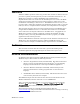
ACKD Message or Device A (Writer) 1 Request 2 Challenge 3 Reply to challenge 4 ACK or Response Device B (reader) Figure 8. Authentication Process If Device A attempts to update an output network variable that is connected to multiple readers, each receiver device generates a different 64-bit random number and sends it in a challenge packet to Device A. Device A must then transform each of these numbers and send a reply to each receiver device.
http://global.ihs.com/doc_detail.cfm?item_s_key=00391891&item_key_date=9711 31&rid=CEA. See Appendix E, Determining Memory Usage for FTXL Applications, on page 181, for information about how to calculate the memory requirements for you FTXL application. Address Table The address table contains the list of network addresses to which the device sends network variable updates or polls, or sends implicitly-addressed application messages.
override the automatic calculation of the table size and specify any number of entries, from 0 to 8192. Recommendation: Whenever possible, use the LonTalk Interface Developer utility-generated size for the alias table. The maximum number of aliases that a device could require depends on its involvement in network variable connections and the characteristics of these connections.
However, it is a common practice to use the “nvi” prefix for input network variables and the "nvo" prefix for output network variables. network input SNVT_count network output SNVT_count nviCount; nvoCount; The LonTalk Interface Developer utility compiles this model file into an application framework that contains, among other things, two global C variables in the FtxlDev.
file. The API uses this table to access the network variables when the application runs. In addition, the application can query the data in this table at runtime. Important: This example is not interoperable because it does not use functional blocks to define the purpose of these network variables. However, this type of declaration can define a functioning device for an initial test application.
Functional Blocks with Configuration Network Variables The following example takes the above example and adds a few configuration properties implemented as configuration network variables. A cp modifier in the network variable declaration makes the network variable a configuration network variable (CPNV). The nv_properties and fb_properties modifiers apply the configuration properties to specific network variables or the functional block.
element of the Meter array of functional blocks, again starting with nvoWattage[0]. The user-defined UCPTcoupling configuration property nciCoupling is shared among all three meters, configuring the meters as three single-phase meters or as one three-phase meter in this example. There is only a single nciCoupling configuration property, and it applies to every element of the array of three UFPTenergyMeter functional blocks.
network output polled eeprom SNVT_elapsed_tm nvoUsage[3]; fblock UFPTenergyMeter { nvoWattage[0] implements nvoWattage; nviAmpere[0] implements nviAmpere; nviVoltage[0] implements nviVoltage; nviCosPhi[0] implements nviCosPhi; nvoUsage[0] implements nvoUsage; } Meter[3] external_name("Meter") fb_properties { static cpCoupling }; The addition of the SNVT_address typed network variable nvoFileDirectory is important for enabling the direct memory files feature for access to the configuration property files.
4 Using the LonTalk Interface Developer Utility You use the model file, described in Chapter 3, and the LonTalk Interface Developer utility to define the network inputs and outputs for your device, and to create your application’s skeleton framework source code. You use this skeleton application framework as the basis for your FTXL application development. The utility also generates device interface files that are used by a network management tool when designing a network that uses your device.
Running the LonTalk Interface Developer You use the LonTalk Interface Developer utility to create the application framework files that are required for your FTXL application. The LonTalk Interface Developer utility also generates the device interface files (*.xif and *.xfb) that can be used by network management tools to design a network that uses your device. To create the device interface data and device interface files for your device, perform the following tasks: 1.
utility’s Model File Selection page, you can specify the name and location of the model file. The location of the LonTalk Interface Developer project file can be the same as your application’s project folder, but you can also generate and maintain the LonTalk Interface Developer’s project in a separate folder, and manually link the latest generated framework with your application by copying or referencing the correct location.
Recommendation: Allow the LonTalk Interface Developer utility to calculate appropriate values for the stack configuration. See Managing Memory on page 46 for more information about these values. Configuring the Buffers From the Buffer Configuration page of the utility, you can specify the number for each of the following application buffer types: • Input buffers • Non-priority output buffers • Priority output buffers You can also specify the number of link-layer buffers.
• The non-volatile data flush guard timeout value • The name for the top-level root segment for the non-volatile data The non-volatile data driver model can be one of the following types, depending on your application’s requirements: • Flash file system (such as the Micrium μC/FS embedded file system) • Flash direct memory (with no file system) if you do not have, or do not want to use, a flash file system for your non-volatile data • User defined if you have another non-volatile data support model
If your company is not a member of the LONMARK International, you can obtain a temporary manufacturer ID from www.lonmark.org/mid. You do not have to join LONMARK International to obtain a temporary manufacturer ID. For prototypes and example applications, you can use the F:FF:FF manufacturer ID, but you should not release a device that uses this non-unique identifier into production.
The LonTalk Interface Developer project directory is automatically included in the compiler search path, and does not need to be specified explicitly. Similarly, the Neuron C Compiler system directories (for header files specified with angled brackets, for example, #include ) are also automatically included in the compiler search path.
• project.xif • project.xfb These files form the FTXL application framework, which defines the FTXL device initialization data and self-identification data for use in initialization phase, including communication parameters and everything you need to begin device development. The framework includes ANSI C type definitions for network variable and configuration property types used with the application, and implements them as global application variables.
The LonCpTypes.h file defines configuration property types, and includes standard or user configuration property types (SCPTs or UCPTs) for configuration properties implemented within configuration files. Either of these files might be empty if your application does not use either network variables or configuration properties. FtxlDev.h The FtxlDev.h file is the main header file that the LonTalk Interface Developer utility produces.
Using Types The LonTalk Interface Developer utility produces type definitions for the network variables and configuration properties in your model file. For maximum portability, all types defined by the utility are based on a small set of host-side equivalents to the built-in Neuron C types. For example, the LonPlatform.h file contains a type definition for a Neuron C signed integer equivalent type called ncsInt. This type must be the equivalent of a Neuron C signed integer, a signed 8-bit scalar.
• The nvoSwitch declaration is based on a structure. The LonTalk Interface Developer utility redefines this structure using built-in Neuron C equivalent types: typedef LON_STRUCT_BEGIN(SNVT_switch){ ncuInt value; ncsInt state; } LON_STRUCT_END(SNVT_switch); Type definitions for structures assume a padding of 0 (zero) bytes and a packing of 1 byte. The LON_STRUCT_BEGIN and LON_STRUCT_END macros enforce platform-specific byte packing and padding. These macros are defined in the LonPlatform.
LON_SET_ATTRIBUTE(var, LON_ALPHA, alpha_flag); These macros are defined in the FtxlTypes.h file. Enumerations The LonTalk Interface Developer utility does not produce enumerations. FTXL requires an enumeration to be of size byte. The ANSI C standard requires that an enumeration be an int, which is larger than one byte for many platforms. An FTXL enumeration uses the LON_ENUM_BEGIN and LON_ENUM_END macros.
This floating-point format can represent numbers with the following characteristics: • ± 1 * 101038 approximate maximum value • ± 1 * 10 −7 approximate relative resolution The float_type structure declaration represents a floating-point number in IEEE 754 single-precision format. This format has one sign bit, eight exponent bits, and 23 mantissa bits; the data is stored in big-endian order. The float_type type is identical to the type used to represent floating-point network variables.
#define LON_MSMANTISSA_FIELD Flags_2 See the IEEE Standard for Binary Floating-Point Arithmetic (ANSI/IEEE Std 754-1985) documentation for more information. Network Variable and Configuration Property Declarations The LonTalk Interface Developer utility generates network variables and configuration properties using the built-in types defined in LonPlatform.h along with the types defined in LonNvTypes.h and LonCpTypes.h. Both network variables and configuration properties are declared in the FtxlDev.
The utility generates a configuration file in FtxlDev.c for the cpLocation configuration property: /* * * Writable configuration parameter value file */ volatile LonWriteableValueFile lonWriteableValueFile = { {{'\x0', '\x0', '\x0', '\x0', '\x0', '\x0', '\x0', '\x0', '\x0', '\x0', '\x0', '\x0', '\x0', '\x0', '\x0', '\x0', '\x0', '\x0', '\x0', '\x0', '\x0', '\x0', '\x0', '\x0', '\x0', '\x0', '\x0', '\x0', '\x0', '\x0', '\x0'}} }; /* * CP template file */ const char lonTemplateFile[] = \ "1.
Similarly, a LonReadOnlyValueFile type is defined and used to declare a lonReadOnlyValueFile variable if the model file declares read-only configuration properties. The LonTalk Interface Developer utility generates resource definitions for configuration properties and network variables defined with the eeprom keyword. Your application must provide sufficient persistent storage for these resources. You can use any type of non-volatile memory, or any other media for persistent data storage.
• Defining the LON_READONLY_FILE_IS_WRITEABLE macro to 1 causes the read-only value file to be writeable by the local application. Because it is now allocated in volatile memory, your driver for nonvolatile data must also be able to read and write the read-only value file. For the network management tool, however, the read-only file remains nonwriteable.
The FtxlTypes.h file defines the bitmasks for these attributes. For example, LON_NV_IS_OUTPUT is the mask for an output network variable, LON_NV_POLLED is the mask for a polled network variable, and so on. The FTXL LonTalk API does not propagate a polled output network variable's value to the network when your application calls the LonPropagateNv() function.
5 Developing an FTXL Application This chapter describes how to develop an FTXL application. It also describes the various tasks performed by the application.
Overview of an FTXL Application This chapter describes how to use the FTXL LonTalk API and the application framework produced by the LonTalk Interface Developer utility to perform the following tasks: • Use the FTXL LonTalk API and FTXL LonTalk protocol stack • Integrate the application with an operating system • Provide persistent storage for non-volatile data • Initialize the FTXL device • Periodically call the FTXL event pump • Send information to other devices using network variables • Rece
Host Application FtxlApi.h FtxlDev.h Application Framework FTXL LonTalk API FTXL LonTalk Protocol Stack Operating System Abstraction Layer Hardware Abstraction Layer FTXL Transceiver ANSI/CEA-709.1 control network Figure 9. The FTXL LonTalk API within the OSI Model The [FTXL]\Core\libFtxl100.
o Future versions or fixes to the FTXL product might affect these API files Callbacks and Events The FTXL LonTalk API uses two types of notifications for occurrences within the system: callbacks and events. The FTXL LonTalk API uses a callback when the API needs a return value from the application immediately. A callback can occur in one of the FTXL LonTalk protocol stack contexts (tasks or threads).
The FTXL OSAL function prototypes are generic, and do not depend on the operating system’s syntax. For example, to create a binary semaphore, your application can call the OsalCreateBinarySemaphore() function, which in turn calls the operating system’s function to create the semaphore. The FTXL OSAL function assigns a pointer to the created semaphore and returns a status variable that indicates whether the function was successful.
current application. The header also includes a checksum to ensure that the data is free of errors. If any of these validations fails, the FTXL LonTalk protocol stack deletes all non-volatile data in the segment and sets the device to the unconfigured state. When data that must be stored persistently is updated in RAM, the FTXL LonTalk protocol stack does not immediately update the corresponding persistent memory.
this function returns FALSE, but if the device was reset while a transaction was in progress, this function returns TRUE and the nonvolatile data segment is considered corrupt, so the restore fails. 2. Calling the LonNvdOpenForRead() callback handler function to open the segment that corresponds to the specified type. 3. Calling the LonNvdRead() callback handler function to read the header of the NVD image.
7. Calling the LonNvdExitTransaction() callback handler function to clear the transaction. 8. Freeing the buffer that contains the serialized image. The FTXL LonTalk protocol stack determines the size of the serialized image and handles the serialization of the data for the LonNvdSegNetworkImage and LonNvdSegNodeDefinition segments, but not for the application-defined LonNvdSegApplicationData segment.
process FTXL events. This function then calls event handler functions (such as LonNvUpdateOccurred() or LonNvUpdateCompleted()). The following sections describe the tasks that an FTXL application performs during its life cycle. Initializing the FTXL Device Before your application initializes the FTXL LonTalk protocol stack, it must initialize the C runtime environment and the operating system. Your application must call the LonInit() function once during device startup.
main thread, the application should implement an infinite loop that waits on this operating system event. Whenever the event is signaled, the application should call the LonEventPump() API function to process FTXL events. You can signal this same operating system event to schedule your main application thread to perform other functions as well. For example, you could signal the operating system event from within an interrupt handler to signal the main application task to process application I/O.
Example: while (1) { // process application-specific data ... if (OsalWaitForEvent(readyHandle, OSAL_WAIT_FOREVER) == OSALSTS_SUCCESS) LonEventPump(); } ... void LonEventReady(void) { OsalSetEvent(readyHandle); } In the example, the readyHandle variable is the handle to an OSAL event; this handle is defined using the OsalCreateEvent() function during the application’s initialization phase, and is signaled by the LonEventReady() callback handler function whenever an event is ready to be processed.
application-specific processing of update completion. Figure 10 shows the control flow for processing a network variable update. FTXL Application FTXL LonTalk Protocol Stack and API LonPropagateNv() Send Network Variable Update to Network Add “Update Complete” Event to Queue LonEventReady() LonEventPump() LonNvUpdateCompleted() Figure 10.
Do not handle an update failure with a repeated propagation; the FTXL LonTalk protocol stack automatically retries a number of times based on the network variable’s retry count. A completion failure generally indicates a problem that should be signaled to the user interface (if any), flagged by an error or alarm output network variable (if any), or by signaled as a comm_failure error through the nvoStatus network variable of the Node Object functional block (if there is one).
If a network variable update is received while the FTXL device is offline, the value of the network variable is updated, but the LonNvUpdateOccurred() event handler function is not called. To process notification of a network variable update, modify the LonNvUpdateOccurred() event handler function (in the FtxlHandlers.c file) to call the appropriate functions in your application. The API calls this function with the index of the updated network variable.
This example extends the previous example and shows how your application can be notified of an update to either network variable. To receive notification of a network variable update, modify the LonNvUpdateOccurred() callback function. In FtxlHandlers.
}; nciGain You can enhance the myController() function to implement the new gain factor: void myController(void) { // nvoWatt = nviAmpere * nviVolt * nciGain.multiplier; LON_SET_UNSIGNED_WORD(nvoWatt, LON_GET_UNSIGNED_WORD(nviAmpere) * LON_GET_UNSIGNED_WORD(nviVolt) * LON_GET_UNSIGNED_WORD(nciGain.multiplier)); // nvoWatt /= nciGain.divider; LON_SET_UNSIGNED_WORD(nvoWatt, LON_GET_UNSIGNED_WORD(nvoWatt) / LON_GET_UNSIGNED_WORD(nciGain.
See The Dynamic Interface Example Application on page 202 for an example application that handles changeable-type network variables.
} nv_type_category_t; This enumeration describes the type (signed short or floating-point, for example), but does not provide information about structure or union fields. To support all scalar types, test for a type_category value between NVT_CAT_SIGNED_CHAR and NVT_UNSIGNED_LONG, plus NVT_CAT_SIGNED_QUAD. The type_length field provides the size of the type in bytes. Multiple changeable-type network variables can share the SCPTnvType configuration property.
then the application must process the type changes for both the network variable and the configuration network variable. If the network variable is a member of a configuration property’s application set where the configuration property is shared among multiple network variables, the application must process the type and length changes for all network variables involved. However, if the configuration property is implemented within a configuration file, no change to the configuration file is required.
callback handler function can report the correct current size for any implemented network variable. Your myGetNvTypeCp() function could handle that mapping. For the convenience of network management tools, you can also declare a SCPTmaxNVLength configuration property to inform the tools of the maximum type length supported by the changeable-type network variable.
network variable is added. On device startup, it calls this function for each dynamic network variable that had been previously defined. • LonNvTypeChanged() The FTXL LonTalk protocol stack calls this function when a dynamic network variable definition is changed. • LonNvDeleted() The FTXL LonTalk protocol stack calls this function when a dynamic network variable is deleted.
Sending an Application Message to the Network Call the LonSendMsg() function to send an application message. This function forwards the message to the FTXL LonTalk protocol stack, which in turn transmits the message on the network. After the message is sent, the FTXL LonTalk protocol stack calls the LonEventReady() callback handler function to inform the application that an event has been enqueued.
management callbacks. These commands are requests for your application to wink, go offline, go online, or reset, and are handled by your LonWink(), LonOffline(), LonOnline(), and LonReset() callback handler functions. Handling Local Network Management Tasks There are various network management tasks that a device can choose to initiate on its own. These are local network management tasks, which are initiated by the FTXL application and implemented by the FTXL LonTalk protocol stack.
utility, might not be able to communicate with a device that is in the extended mode. To return an FTXL device to the legacy mode, rather than the extended mode, perform one of the following tasks: • Re-run the LonTalk Interface Developer utility to generate a new signature for the device, and rebuild and load the application image. • Send the NM_NODE::NM_INITIALIZE extended network management command to the device. • Erase the non-volatile memory for the device.
You do not generally need to modify the code that the LonTalk Interface Developer utility generates (in FtxlDev.c) or the LonMemoryRead() and LonMemoryWrite() callback handler functions (in FtxlHandlers.c). The DMF Memory Window To the network management tool, all content of the DMF memory window is presented as a continuous area of RAM memory in the virtual DMF memory space.
FTXL network address space (Neuron addresses in big-endian notation) Virtual address space: defined host-side, using virtual Smart Transceiver addresses in host’s byte order Physical host address space SNVT_address File directory FTXL Transceiver LON_DMF_WINDOW_START Maximum range: 0x0001 – 0xFFFF Template file File directory LON_DMF_WINDOW_USAGE Registered Memory Window Template file Writable value file Read-only value file Read-only value file unused Writable value file Address translation pro
File Directory The LonTalk Interface Developer utility produces a configurable file directory structure, which supports: • Using named or unnamed files (the DMF framework uses unnamed files by default, whereas FTP uses named files) • Up to 64 KB of data for each file • For the DMF framework: Up to a total of 64 KB for all files plus the file directory itself • For FTP: unlimited size The utility initializes the file directory depending on the chosen access method.
6 Working with the Nios II Development Environment This chapter describes how to set up the Nios II IDE for building and running your application for FTXL. It also describes how to import or create the application, and how to customize it. See Appendix G, Example FTXL Applications, on page 195, for information about working with the Nios II IDE for the example applications.
Development Tools To develop your FTXL application, you use version 7.2 or later of the Altera Complete Design Suite, as listed in Table 8. You can obtain the Altera Complete Design Suite on DVD-ROM from Altera Corporation, or you can download the Web Edition of the tools from https://www.altera.com/support/software/download/nios2/dnl-nios2.jsp. Table 8.
Using a Device Programmer for the FPGA Device To load your hardware design, software application, and the FTXL LonTalk protocol stack, into the FPGA device, you can use a device programmer, such as the Altera USB-Blaster download cable, as described in Table 9. Table 9. Device Programmer for the Nios II Processor Altera USB-Blaster Download Cable The USB-Blaster download cable interfaces to a standard PC USB port. This cable drives configuration or programming data from the PC to the device.
application consists of the following components, all of which need to be added to the Nios II IDE for FTXL application development: • Your application code • The application framework files generated by the LonTalk Interface Developer utility • The FTXL LonTalk protocol stack library, which includes the FTXL LonTalk API • The FTXL system library, which includes the system description for the Nios II processor and associated hardware To set up the Nios II IDE to use the example FTXL applications, pe
5. Specify the target hardware. Click Browse in the Select Target Hardware area to open the Select Target Hardware dialog. a. In the Select Target Hardware dialog, browse to the directory that contains your project’s hardware description files and select the appropriate SOPC Builder system file (*.ptf). b. Click Open to select the file and close the Select Target Hardware dialog. 6. Do not modify the CPU field in the Select Target Hardware area; the name of the CPU is contained in the project’s *.ptf file.
To customize the system library properties for the operating system: 1. Right-click the system library from the Nios II C/C++ Projects pane and select Properties to open the Properties window. 2. In the Properties window, click RTOS Options to open the Options dialog for your operating system. 3. Within the Options dialog, set the appropriate values.
f. In the Properties window, click Apply to save these settings, then click OK to close the dialog. Other options and properties can be set to their default values. Building the Application Image After you first create your application project in the Nios II IDE, you should perform a clean build to remove obsolete files and to fix any problems from a previously built state. To clean the FTXL software image: 1. Select Project → Clean to open the Clean window. 2.
b. Load the hardware image for the Nios II processor into the FPGA device, as described in the FTXL Hardware Guide. Leave Quartus II Programmer window open. 5. Select Tools → Flash Programmer to open the Flash Programmer window. 6. In the Flash Programmer window, right-click Flash Programmer in the left-hand pane and select New to create a configuration for the selected project. 7. Select Program software project into flash memory.
4. If you have a valid Nios II development license, and have already loaded the configuration data (the JTAG Indirect Configuration (*.jic) file or SRAM object file (*.sof)) into the FPGA device, proceed to step 6. 5. If you do not have a valid Nios II development license, or have not loaded the configuration data into the FPGA device: a. The Nios II IDE displays the following text in the Console window: There are no Nios II CPUs with debug modules available which match the values specified.
• The application itself, including implementations of the event handler functions and callback handler functions of the FTXL LonTalk API. • The FTXL non-volatile data driver. You can modify the driver from the example applications. • The FTXL operating system abstraction layer. You can modify the FTXL OSAL from the example applications to provide support for an operating system other than the Micrium μC/OS-II operating system or to change the settings for the operating system.
A LonTalk Interface Developer Command Line Usage This appendix describes the command-line interface for the LonTalk Interface Developer utility. You can use this interface for script-driven or other automation uses of the LonTalk Interface Developer utility.
Overview The LonTalk Interface Developer utility consists of two main components: • The LonTalk Interface Developer graphical user interface (GUI), which collects your preferences and displays the results • The LonTalk Interface Builder, which processes the data from the GUI and generates the required output files If you plan to run the LonTalk Interface Developer utility in an unattended mode, for example as part of an automated build process, you can use the command-line interface to the LonTalk Inter
are yes, on, 1, +, no, off, 0, - (a minus sign or dash). Examples: libf -–verbosecomments=yes libf --verbosecomments • Commands can be read from the command line or from a command file (script file). A command file contains empty lines, lines starting with a semicolon (comment lines), or lines containing one command switch on each line (with value as applicable). The file extension can be any characters, but it is recommended that you use the “.libf” extension.
Command Switch Long Form Short Form --buffer -B Implement specified number of buffers of the specified type --clock -c Set the FTXL Transceiver clock rate (in MHz) --define -D Define a specified preprocessor symbol (without value) --defloc Description Location of an optional default command file --dmfsize -z Override size of the direct memory file memory window --dmfstart -a Override start address of the direct memory file memory window --domains -d Implement domain table with specifie
Command Switch Long Form Short Form Description --source -n Use the specified model file --spdelay -p Set the service pin notification delay (255=default, 0=off) --txdb -t Manage specified number of transmit transaction records --txttl -T Let transmit transactions expire after specified number of microseconds --verbose -v Run with verbosity level 0 (normal), 1 (verbose), or 2 (trace) --verbosecomments -V Generate verbose comments --warning Display specified message type as a warning S
Note that the type and number for the --buffer switch are separated by a period. You can include several buffer specifications within a single --buffer switch, separated by commas, or with multiple --buffer switches. For example: --buffer=ai.5,ao.3 --buffer=ai.5 --buffer=ao.3 Table 11.
Buffer Type Network output priority buffers Primary Specification Alternate Specifications Valid Values nop netoutputprio 1 to 100 netoutprio Default: 3 netprio network-priorityoutput The application buffers (ai, ao, and aop) all have a range of 1 to 100 for the allowable number of buffers. You can set priority buffers to a count of 0 (zero), but you must specify at least one non-priority buffer in both directions (input and output).
B Model File Compiler Directives This Appendix lists the compiler directives that can be included in a model file. Model files are described in Chapter 3, Creating a Model File, on page 23.
Using Model File Compiler Directives ANSI C permits compiler extensions through the #pragma directive. These directives are implementation-specific. The ANSI standard states that a compiler can define any sort of language extensions through the use of these directives. Unknown directives can be ignored or discarded. The Neuron C compiler issues warning messages for unrecognized directives.
Important: Configuration property re-ordering and merging can reduce the memory required for the template file, but can also result in slower access to the application’s configuration properties by network management tools. This can potentially cause a significant increase in the time required to commission your device, especially on low-bandwidth channel types. You should typically only use configuration property re-ordering and merging if you must conserve memory.
#pragma set_guidelines_version string The Neuron C 2.1 compiler generates LONMARK information in the device’s XIF file and in the device’s SIDATA (stored in device program memory). By default, the compiler uses “3.3” as the string to identify the LONMARK guidelines version to which the device conforms. To override this default, specify the overriding value in a string constant following the pragma name, as shown. For example, a program could specify #pragma set_guidelines_version “3.
#pragma disable_warning number #pragma enable_warning number Controls the compiler's printing of individual warning messages. Warning messages generally indicate a problem in the model file, or a place where the code could be improved. Warning messages are on by default. These pragmas can be intermixed multiple times throughout a model file to turn informational message printing on and off as needed. The number parameter refers to a specific warning number, for example #pragma disable_warning 123.
C Neuron C Syntax for the Model File This Appendix lists the Neuron C syntax for the allowable statements of a model file.
Functional Block Syntax fblock FPT-identifier { fblock-member-list } identifier [ array-bounds ] [ ext-name ] [ fb-property-list ] ; fblock-member-list : fblock-member-list ; fblock-member fblock-member fblock-member : nv-reference implements member-name nv-reference impl-specific impl-specific : implementation_specific ( const-expr ) member-name nv-reference : nv-identifier array-index nv-identifier array-index : [ const-expr ] array-bounds : [ const-expr ] ext-name : external_name ( concaten
referenced by the fblock must be declared as an array of at least the same size. When implementing an fblock array's member with an array network variable element, the starting index of the first network variable array element in the range of array elements must be provided in the implements statement. The Neuron C compiler automatically adds the following network variable array elements to the fblock array elements, distributing the elements consecutively.
implementation_specific keyword, followed by a unique index number, and a unique name. Each network variable in a functional profile assigns an index number and a member name to each abstract network variable member of the profile, and the implementation-specific member cannot use any of the index numbers or member names that the profile has already used. Examples Example 1: The following example declares a functional block with a single network variable.
Functional Block Properties Syntax fb_properties { property-reference-list } property-reference-list : property-reference-list , property-reference property-reference property-reference : property-identifier [ = initializer ] [ range-mod ] property-identifier [ range-mod ] [ = initializer ] range-mod : range_mod_string ( concatenated-string-constant ) property-identifier : [ property-modifier ] identifier [ constant-expression ] [ property-modifier ] identifier property-modifier : static | global K
has a range modification, then all members must have a range modification specified. In this case, each range modification pair is delimited by the ASCII vertical bar character '|'. To specify no range modification for a member of a structure (that is, revert to the default for that member), encode the field as '|'. Use the same encoding for structure members that cannot have their ranges modified due to their data type. The '|' encoding is only allowed for members of structures.
of the nvoData network variable array), and four offset CP family members (SCPToffset), one for each member of each fblock array. It also instantiates a total of two gain control CP family members (SCPTgain), one for MyFb1, and one for MyFb2. Finally, it instantiates a single location CP family member (SCPTlocation) that is shared by MyFb1 and MyFb2.
network output SNVT_amp nvoAmpere; network output polled SNVT_time_stamp nvoInstallDate; fblock SFPTopenLoopSensor { nvoAmpere implements nvoValue; nvoInstallDate implementation_specific(128) nvoInstall; } fbAmpereMeter external_name("AmpereMeter") fb_properties { cpDefaultOutput, // optional CP cpDisplayBrightness = {50.
sync | synchronized Specifies that all values assigned to this network variable must be propagated, and in their original order. This flag is passed on to your FTXL application, and must be enforced by your application. This keyword is mutually exclusive with the polled keyword. polled For an output network variable, specifies that the value of the network variable is to be sent only in response to a poll request from a device that reads this network variable.
In an application that uses compiler-generated SD data, you can still specify additional SD data with the sd_string() modifier. The compiler appends this additional SD information to the compiler-generated SD data, but it will be separated from the compiler-generated information with a semicolon. SD data that appears after the semicolon is treated as a comment and is not included in the device’s interoperable interface.
Recommendation: Use a SNVT or SCPT if one is available that matches your data because SNVTs and SCPTs can provide interoperability with other devices. • A user network variable type (UNVT) or user configuration property type (UCPT) defined in a user resource file. You can use the NodeBuilder Resource Editor to create custom UNVTs and UCPTs, and to view the available UNVTs and UCPTs in your resource files. Use a UNVT or UCPT if you cannot find an appropriate SNVT or SCPT for your data.
network variables. This keyword is not required for model files. Names of array elements are automatically expanded by the LonTalk Interface Developer compiler. offline Specifies that a network management tool must take this device offline, or ensure that the device is already offline, before updating the network variable. Do not use this feature in the bind_info for a configuration network variable that is declared using the config_prop or cp keyword. Instead, use the offline option in the cp_info.
A network variable connection is authenticated only if the readers and writers have the authenticated keywords specified. However, if only the originator of a network variable update or poll uses the keyword, the connection is authenticated (although the update does take place). See Using Authentication on page 44 for more information about authentication. The default is nonauth (config). Recommendation: Use the acknowledged service with authenticated updates.
The Network Variable Initializer initial-value or initializer-list Specifies an initial value (or values) for the network variable. All network variables, especially input network variables, should be initialized to a reasonable default value.
Network variable properties can be shared between two or more network variables. The use of the global keyword creates a CP family member that is shared between two or more network variables. The use of the static keyword creates a CP family member that is shared between all the members of a network variable array, but not with any other network variables outside the array.
cp_family Declares the configuration property as part of a configuration file. The cp_family declaration is repeatable. The declaration can be repeated two or more times, and, as long as the duplicated declarations match in every regard, the compiler treats these as a single declaration. The alternative to declaring a configuration property as part of a configuration file is to declare a configuration network variable, as described in Declaring a Configuration Network Variable on page 143.
network database. This specification is used for configuration properties that must be managed by the device, such as a setpoint that is updated by a local operator interface on the device. This option requires the CP family or configuration property network variable to be declared as const. manufacturing_only Specifies a factory setting that can be read or written when the device is manufactured, but is not normally (or ever) modified in the field.
specified. In this case, each range modification pair is delimited by the ASCII vertical bar character '|'. To specify no range modification for a member of a structure (that is, revert to the default for that member), encode the field as '|'. Use the same encoding for structure members that cannot have their ranges modified due to their data type. The '|' encoding is only allowed for members of structures.
The compiler uses the first rule in this list that applies to the configuration property. These initialization rules are used to set the initial value that are loaded in the value file from the linked image, as well as the value file stored in the device interface file. A network management tool can use the initial value as a default value, and might at times reset the configuration properties (or a subset of them) back to the default values.
The syntax for declaring a device property list is: device_properties { property-reference-list } ; property-reference-list : property-reference-list , property-reference property-reference property-reference : property-identifier [ = initializer ] [ range-mod ] property-identifier [ range-mod ] [ = initializer ] range-mod : range_mod_string ( concatenated-string-constant ) property-identifier : identifier [ constant-expression ] identifier The device property list begins with the device_properties key
// empty string initializer with its own }; Message Tag Syntax msg_tag [ connection-info ] tag-identifier [, tag-identifier ...] ; Keywords The connection-info field is an optional specification for connection options, and includes the following keywords: msg_tag Declares a message tag with the specified tag-identifier.
D FTXL LonTalk API This Appendix describes the API functions, event handler functions, and callback handler functions that are included with the FTXL LonTalk API. It also describes the FTXL operating system abstraction layer (OSAL) and hardware abstraction layer (HAL) functions.
Introduction The FTXL LonTalk API provides the functions that you call from your FTXL application to send and receive information to and from a LONWORKS network. The API also defines the event handler functions and callback handler functions that your FTXL application must provide to handle LONWORKS events from the network and FTXL LonTalk protocol stack. Because each FTXL application handles these events and callbacks in its own specific way, you need to modify the event and callback handler functions.
• API source code for the example applications: Start → Programs → Echelon FTXL Developer’s Kit → Source Code FTXL LonTalk API Functions The FTXL LonTalk API includes functions for managing network data, the FTXL device, and non-volatile data. Commonly Used FTXL LonTalk API Functions Table 12 lists API functions that you will most likely use in your FTXL application. Table 12.
Table 13. Other FTXL LonTalk API Functions Function Description LonFreeNvTypeData() Frees internal buffers that were allocated by a call to the LonQueryNvType() function. LonGetDeclaredNvSize() Gets the declared size for a network variable. LonGetNvValue() Gets a pointer to the value for a network variable. This function is required for dynamic network variables, but could be used for any network variable. LonGetUniqueId() Gets the unique ID (Neuron ID) value of the FTXL Transceiver.
Function Description LonSendResponse() Sends an application message response to a request message. The FTXL application calls LonSendResponse() in response to a LonMsgArrived() event handler function. Non-Volatile Data API Functions Table 15 lists the FTXL LonTalk API functions that are used for implementing support for non-volatile data. Table 15.
Function Description LonQueryConfigData() Queries local configuration data on the FTXL device. LonQueryDomainConfig() Retrieves a copy of the local domain table record from the FTXL device. LonQueryNvConfig() Queries configuration data for theFTXL device’s network variable table. LonQueryStatus() Requests local status and statistics. LonQueryTransceiverStatus() Requests the local status of the FTXL Transceiver.
Table 17. Commonly Used FTXL Event Handler Functions Function Description LonNvUpdateCompleted() Indicates that either an update network variable or a poll network variable call is completed. LonNvUpdateOccurred() Indicates that a network variable update request from the network has been processed by the FTXL LonTalk API. This call indicates that the network variable value has already been updated, and allows your host application to perform any additional processing, if necessary.
Dynamic Network Variable Event Handler Functions Table 18 lists the event handler functions that are called by the FTXL LonTalk API to process dynamic network variables. See Handling Dynamic Network Variables on page 92 for more information about using these functions. Table 18. Dynamic Network Variable Event Handler Functions Function Description LonNvAdded() Indicates that a dynamic network variable has been added. LonNvDeleted() Indicates that a dynamic network variable has been deleted.
Function Description LonResponseArrived() Indicates that an application message response has arrived from the network. This function performs any application-specific processing required for the message. Non-Volatile Data Event Handler Functions The FTXL LonTalk API provides the event handler function listed in Table 20 to support non-volatile data. Table 20.
Function Description LonEventReady() Indicates that a network event is ready to be processed. The FTXL LonTalk protocol stack calls this callback handler function to indicate that a network event is ready to be processed, and that the main application should call the LonEventPump() function. However, the LonEventReady() function should not call the LonEventPump() function directly. Typically, the LonEventReady() callback signals an operating system event that the main application task waits upon.
Function Description LonNvdDelete() Indicates a request to delete a non-volatile data segment. LonNvdDeserializeSegment() Indicates a request to update the FTXL device’s control structures from the serialized application’s data segment. LonNvdEnterTransaction() Indicates a request to begin a transaction for the non-volatile data segment. LonNvdExitTransaction() Indicates a request to complete a transaction for the non-volatile data segment.
• HTML API documentation: Start → Programs → Echelon FTXL Developer’s Kit → Documentation → API Reference • API source code for the example applications: Start → Programs → Echelon FTXL Developer’s Kit → Source Code The following sections provide an overview of the functions that the FTXL OSAL provides. Managing Critical Sections To manage critical sections, the FTXL OSAL provides the functions listed in Table 24. Table 24.
Function Description OsalDeleteEvent() Deletes an event. OsalSetEvent() Sets an event. OsalWaitForEvent() Waits for an event. Managing System Timing To manage system timing, the FTXL OSAL provides the functions listed in Table 27. Table 27. FTXL OSAL Timing Functions Function Description OsalGetTickCount() Gets the current system tick count. OsalGetTicksPerSecond() Gets the number of ticks in a second.
Table 29. FTXL OSAL Debug Functions Function Description OsalClearStatistics() Clears the current operating system statistics. OsalGetLastOsError() Gets the most recent error from the operating system. OsalGetStatistics() Gets operating system statistics. OsalGetTraceLevel() Gets the current OSAL tracing level. OsalSetTraceLevel() Sets the OSAL tracing level. Configuring the Operating System The FTXL OSAL defines resources for an operating system.
Resource Number Notes Events 10 Modify the number of events, if needed, within the operating-system settings.
Figure 13. FTXL Abstract Priorities Before you can instantiate a task within an application, you must map the FTXL OSAL abstract priorities to the operating system’s priorities. The abstract priorities are defined in the FtxlOsal.h file that is copied to your project directory by the LonTalk Interface Developer utility. To map the FTXL OSAL abstract priorities to the operating system’s priorities, use the macros that are defined in the FtxlOsal.h file, as listed in Table 32.
OS_LOW_APPLICATION_PRIORITY_BASE Defines the highest OS priority used for application tasks running at a lower priority than any FTXL LonTalk protocol stack tasks. Figure 14.
Figure 15. Defined Symbols in the Project Properties Dialog Similarly, if you want to support any application tasks in the high priority class, you must override the definition of the NUM_RESERVED_HIGH_PRIORITY_APPLICATION_TASKS macro.
priority tasks (OS_HIGH_PRIORITY_BASE) set to 4. The figure assumes that low numbers represent high priorities. The cross-hatch shaded numbers represent the desired configuration of one high-priority application task (at priority 7), two medium-priority application tasks (at priorities 13 and 14), and three low-priority application tasks (at priorities 17, 18, and 19).
Lowest Assignable Task Priority The μC/OS-II operating system uses the lowest task priority for the idle task, and it uses the second lowest task priority for the statistics task (if the statistics task is enabled). The documentation for the μC/OS-II operating system recommends that the application not use the highest four priorities (0 through 3) or the lowest four priorities (OS_LOWEST_PRIO-3 through OS_LOWEST_PRIO). By default, the definitions in the FtxlOsal.
Maximum Number of Event Control Blocks The μC/OS-II operating system uses event control blocks for the FTXL OSAL critical sections, binary semaphores, and events. You define the maximum number of event control blocks as the sum of the number of critical sections, binary semaphores, and events. See Determining Resource Requirements on page 160 for information about how to calculate the number of each of these resources.
Table 33. MicroC/OS-II General Options Option Setting for FTXL Applications Maximum number of tasks 13 or higher See Maximum Number of Tasks on page 165. Lowest assignable priority 18 or higher See Lowest Assignable Task Priority on page 166.
Figure 18. MicroC/OS-II General Options Page Event Flags Table 34 describes the event flag options for the μC/OS-II operating system. Table 34.
Option Setting for FTXL Applications Size of name of Event Flag group 0 or larger Event flag bits 8 or more Figure 19 shows the MicroC/OS-II Event Flags page of the MicroC/OS-II RTOS Options window. The figure shows the settings used by the example applications. Figure 19. MicroC/OS-II Event Flags Page Mutex FTXL applications do not use mutex resources. Table 35 describes the mutex options for the μC/OS-II operating system. Table 35.
Option Setting for FTXL Applications Include code for OSMutexDel() Not required Include code for OSMutexQuery() Not required Semaphores Table 36 describes the semaphore options for the μC/OS-II operating system. Table 36.
Figure 20. MicroC/OS-II Semaphores Page Mailboxes FTXL applications do not use mailbox resources. Table 37 describes the mailbox options for the μC/OS-II operating system. Table 37.
Queues FTXL applications do not use queue resources. Table 38 describes the queue options for the μC/OS-II operating system. Table 38.
Option Setting for FTXL Applications Enable debug variables Not required Include code for OSSchedLock() and OSSchedUnlock() Not required Enable tick stepping feature for uCOSView Not required Enable statistics task Not required Check task stacks from statistics task Not required Statistics task stack size Not required Idle task stack size 512 Maximum number of Event Control blocks 102 or more Size of Semaphore, Mutex, Mailbox or Queue name See Maximum Number of Event Control Blocks on pag
Figure 21. MicroC/OS-II Miscellaneous Page Task Management Table 41 describes the task-management options for the μC/OS-II operating system. Table 41.
Option Setting for FTXL Applications Include code for OSTaskQuery() Required Include code for OSTaskSuspend() and OSTaskResume() Not required Include code for OSTaskSwHook() Required Size of task name 0 or larger Figure 22 shows the MicroC/OS-II Task Management page of the MicroC/OS-II RTOS Options window. Figure 22. MicroC/OS-II Task Management Page Time Management Table 42 on page 177 describes the time-management options for the μC/OS-II operating system.
Table 42. MicroC/OS-II Time Management Options Option Setting for FTXL Applications Include code for OSTimeDlyHMSM() Not required Include code for OSTimeDlyResume() Not required Include code for OSTimeGet() and OSTimeSet() Required Include code for OSTimeTickHook() Not required Figure 23 shows the MicroC/OS-II Time Management page of the MicroC/OS-II RTOS Options window. Figure 23. MicroC/OS-II Time Management Page Timer Management FTXL applications do not use timer-management resources.
Table 43.
Table 44. FTXL HAL Transceiver Functions Function Description LonAssertTransceiverReset() Asserts the FTXL Transceiver’s RESET~ pin, which causes the Transceiver to reset. LonDeassertTransceiverReset() Deasserts the FTXL Transceiver’s RESET~ pin, which causes the Transceiver to complete post-reset processing. LonReadTransceiverDataRegister() Reads the FTXL Transceiver’s data register. LonReadTransceiverReset() Reads the state of the FTXL Transceiver’s RESET~ pin.
Function Description LonDriverTransceiverIrq() The main body of the ISR for processing input from the FTXL Transceiver’s IRQ~ pin. This function is implemented in the FTXL library, and is called by an interrupt routine defined in the FTXL HAL. LonEnableInterrupt() Enables the FTXL ISRs. LonRegisterIsr() Registers the FTXL ISRs with the Altera HAL.
E Determining Memory Usage for FTXL Applications This Appendix describes how much volatile and non-volatile memory an FTXL application requires, and how to determine the application’s memory requirements.
Overview The FTXL LonTalk protocol stack allocates memory dynamically, so a direct measurement of the memory usage might lead to an underestimate for memory usage, especially for peak usage conditions. This appendix provides both static code analysis and runtime measurements so that you can calculate more reliable memory usage estimates. Total Memory Use After you create your FTXL application and compile it, you can determine how much flash memory and RAM the application requires.
call to the LonInit() function (you could also call it after the FTXL device is commissioned or during peak activity). For the FTXL_Simple_0.elf file shown above, the uordblocks field is 134 244 bytes (131 KB). Thus, the RAM requirement for the application includes the 593 496 bytes from the flash requirement plus the 134 244 bytes from the heap requirement, for a total RAM requirement of 727 740 bytes (711 KB).
Table 48. RAM Usage per Application Buffer Application Buffer Type Bytes Required Input buffer 1710 Output nonpriority buffer 1118 Output priority buffer 1118 The default numbers for each type of buffer are: 5 input buffers, 5 output nonpriority buffers, and 1 output priority buffer. Thus, the RAM usage for the default number of application buffers is approximately 15 KB.
required for each type of LONWORKS resource. The number of bytes required for each type of resource is an estimate; you should round these numbers upward when you use them in flash memory usage calculations. Table 50.
The flash memory implementation in the FtxlNvdFlashDirect.c file requires that each data segment begin on a flash sector boundary. Depending on the flash sector size, this requirement can increase the total flash memory needed for the application. Table 51 describes the amount of non-volatile memory required for the network image. Table 51.
Table 53.
Table 54.
2500 2000 1500 Memory (KB) RAM 1000 Flash 500 0 10 100 250 500 1000 2000 4000 Number of Network Variables Figure 24.
F Downloading an FTXL Application Over the Network This Appendix describes considerations for designing an FTXL application that allows application updates over the network.
Overview For a Neuron-hosted device, you can update the application image over the network using LNS or another network management tool. However, you cannot use the same tools or technique to update an FTXL application image over the network. Many FTXL devices do not require application updates over the network, but for those that do, this appendix describes considerations for adding this capability to the device.
should also inform the user of its state. During this stage, the FTXL device should verify that the application to be downloaded can run on the device platform (using the FPGA ID or similar mechanism), and verify that the application image is from a trusted source (for example, by using an encrypted signature). 2. Download the application. A reliable and efficient data transfer mechanism should be used.
minimum, the FTXL application should reserve enough RAM to buffer two flash sectors. When one sector has been completely received, the application should write it to flash in a background process. If the write is not complete when the second buffer is filled, the FTXL application must tell the application download utility to delay additional updates until the application is ready to receive the data.
G Example FTXL Applications This Appendix describes the example applications that are included in the FTXL Developer’s Kit. This Appendix describes each application’s design, main() and event handler functions, and model file. It also describes how to build and load the application images and run the example applications.
Overview of the Example Applications The FTXL Developer’s Kit includes two example applications: the simple example and a dynamic interface example. The simple example application is a very simple application that simulates a voltage amplifier device. This device receives an input voltage value, multiplies the value by 2, and returns the new output value.
Table 56. FTXL Dynamic Interface Example Files File Name Description Dynamic Interface Example.lidprj LonTalk Interface Developer project file Dynamic Interface Example.nc Model file for the application FtxlHandlers.c C file for the callback handler functions for the application main.c Main application file readme.txt Readme file for the project, including a brief description of the project, and hardware and operating system requirements SNVT_RQ.
Main Function The main() function is in the main.c file.
• Creates the “event ready” event using the FTXL OSAL OsalCreateEvent() function. The LonEventReady() callback handler function uses this event to wake up the application task to process FTXL network events. • Calls the LonInit() function to initialize the FTXL LonTalk protocol stack and FTXL Transceiver. If this function fails, the appTask() function calls the FTXL OSAL OsalDeleteEvent() function to delete the “event ready” event.
The FtxlHandlers.c file contains the modified LonNvUpdateOccurred() function, which is called when the host processor receives a network-variable update. This function simply calls the myNvUpdateOccurred() function in the main.c file that provides the application-specific behavior. This functional separation approach keeps changes to the LonTalk Interface Developer utility-generated files to a minimum.
• ProcessOnlineEvent(): Calls the ProcessNviVoltUpdate() function when the device goes online. These functions are defined in the main.c file. Callback Handler Function To signal to the main application the occurrence of certain types of events, the FTXL LonTalk API calls specific callback handler functions. For the simple voltage actuator example application, only one of the API’s callback handler functions has been implemented to provide application-specific behavior. The FtxlHandlers.
For more information about creating and using a model file, see Creating a Model File on page 23. To change the LONWORKS interface and functionality of the example application, perform the following steps: 1. Define the interface in the Simple Example.nc model file. 2. Run the LonTalk Interface Developer utility to generate an updated application framework. 3. Make appropriate changes to the callback handler functions in the FtxlHandlers.c file or the main.c file. 4. Rebuild the project. 5.
SNVT_volt_mil type. Any attempt to change the NV to an unsupported type causes the device to reject the change and to revert the nciNvType CPNV to its last-known good value. The design of the example application is relatively simple. It includes a single C source file (main.c), along with the FTXL LonTalk API files generated by the LonTalk Interface Developer utility and a version of FtxlHandlers.c that has been customized for this example application.
LON_SET_UNSIGNED_WORD(FbStatus[fbIndex].object_id, fbIndex); } /* Initialize the circuitMap. Initially there are no * members. If any dynamic NVs have been defined, the * FTXL LonTalk API will call the LonNvAdded event * handler during LonInit, which will in turn call * myNvAdded. The myNvAdded function will add the NV to * circuitMap assuming that it follows the naming * convention and its type is SNVT_amp.
Although the main() and appTask() functions for this application are part of an example, you can use the same basic algorithmic approach for a production-level application. The the appTask() function is shown below. /* The application task initializes the FTXL LonTalk * protocol stack and implements the main control loop. * The bulk of the application processing is performed in * the myNvUpdateOccurred event handler.
This functional separation approach keeps changes to the LonTalk Interface Developer utility-generated files to a minimum. For a production-level application, you can place application-specific code wherever your application design requires it. For the dynamic interface example application, the following API event handler functions have been implemented to provide application-specific behavior: • LonReset(): This function is called when the device is reset. This function calls myReset() in main.c.
• • Checks whether the object index represents a supported object: o For non-supported objects, sets the object status to invalid. o For supported objects: Checks whether the command applies to all objects or to a specified functional block Performs the specified command (implemented in a switch statement based on the nviRequest.
LonBool processActuatorInputs = FALSE; unsigned index = LON_GET_UNSIGNED_WORD(nviRequest.object_id); memset((void *)&nvoStatus, 0, sizeof(nvoStatus)); LON_SET_UNSIGNED_WORD(nvoStatus.object_id, index); if (index >= FBIDX_count) { /* We don't support this object - flag it as an * invalid ID. */ LON_SET_ATTRIBUTE(nvoStatus, LON_INVALIDID, 1); } else { /* If reportStatus is TRUE, set the objectStatus to * the status of the specified functional block.
/* Update the status. If the object is not the * node object, just return the current status * of the object. Special processing below for * node object only. */ if (index == FBIDX_NodeObject) { /* When requesting the status of the node * object, return a status that represents * the OR of the statuses of all functional * blocks. * Don't report the status of the node object * - use the summary below. */ reportStatus = FALSE; for (i = start; i <= limit; i++) { nvoStatus.Flags_1 |= FbStatus[i].
{ /* Actuator was disabled, but is now * enabled. Process current input values.
break; } } myNvAdded() The myNvAdded() function calls the UpdateCircuitMap() utility function to update the logical circuit for the added network variable. The myNvAdded() function is shown below. /* This function is called by the FTXL LonNvAdded event * handler, indicating that a dynamic network variable has * been added. It is also called during LonInit for each * dynamic NV that is found in the FTXL persistent storage.
void myNvDeleted(const unsigned index) { LonByte oldCircuitId = circuitMap[index].circuitId; if (oldCircuitId != NO_CIRCUIT) { /* Remove the NV from the circuit. */ circuitMap[index].circuitId = NO_CIRCUIT; /* Update the output NV of the circuit to which this NV * used to belong. */ UpdateCircuitOutput(oldCircuitId); } } myReset() The myReset() function calls the ProcessOnlineEvent() utility function to process changes to input network variables and configuration property values.
Application-Specific Utility Functions The dynamic interface example application includes the following applicationspecific utility functions: • ProcessNviVoltUpdate(): Performs range checking for the network variables, sets the output network variable to double the value of the input network variable, and propagates the output network variable to the network. • ProcessOnlineEvent(): Calls the ProcessNviVoltUpdate() function when the device goes online.
void myEventReady(void) { /* Signal application task so that it can process the * event. */ OsalSetEvent(eventReadyHandle); } Model File The model file, Dynamic Interface Example.nc, defines the LONWORKS interface for the example FTXL device. The model file defines two functional blocks: NodeObject and VoltActuator. The NodeObject functional block allows a network management tool to enable or disable the functional blocks for the FTXL device.
fblock SFPTclosedLoopActuator { nviVolt implements nviValue; nvoVoltFb implements nvoValueFb; } voltActuator external_name("VoltActuator"); For more information about creating and using a model file, see Creating a Model File on page 23. To change the LONWORKS interface and functionality of the example application, perform the following steps: 1. Define the interface in the Dynamic Interface Example.nc model file. 2. Run the LonTalk Interface Developer utility to generate an updated application framework.
3. Optional: Enter a project name in the Name field. The default name is FTXL_Simple_0. 4. Specify a location for this project (such as C:\MyFtxl) by selecting the Specify Location checkbox and specifying the location in the Location field. The directory name must not contain spaces. If you use the default location, your source files will be placed in the project workspace directory. 5. Specify the target hardware. Click Browse in the Select Target Hardware area to open the Select Target Hardware dialog. a.
Figure 25. New Project Window for the FTXL Simple Project Perform the same steps to create a new project for the dynamic interface example application, but in step 2, select the FTXL Dynamic Interface project. Both example applications use the same target hardware. Running the LonTalk Interface Developer Utility Before you can compile the newly created project, you must run the LonTalk Interface Developer utility to generate application-specific files and copy other required files to the project directory.
2. From the Welcome to LonTalk Interface Developer page of the utility, click Browse to open the appropriate project file: • [MyFTXL]\FTXL_Simple_0\Simple Example.lidprj • [MyFTXL]\FTXL_DynamicInterface_0\Dynamic Interface Example.lidprj where [MyFTXL] is the location that you specified for the project when you created it within the Nios IDE. The subdirectory name is the same as the project name that you specified when you created the project. 3.
1. Start the Nios II EDS IDE. 2. Ensure that the workspace includes the example application project that you want to build. 3. Select Project → Build Project or Project → Build All. You can also rightclick the project folder from the Nios II C/C++ Projects pane and select Build Project. The first build for a new project can take a few minutes. To build the application automatically, see Building the Application Image on page 107.
e. Select Program FPGA configuration data into hardware-image region of flash memory to load the hardware design into flash along with the software design. If necessary, specify the following information for the FPGA configuration: i. Click Browse next to the FPGA Configuration (SOF) dropdown list box to select the DBC2C20_FTXL.sof hardware design file from the [Altera]\nios2eds\examples\vhdl\DBC2C20_FTXL\Stan dard directory. ii. Select Nios II EP2C35 epcs from the Hardware Image dropdown list box. iii.
5. If you have a valid Nios II development license, and have already loaded the configuration data into the Cyclone II FPGA, proceed to step 7. 6. If you do not have a valid Nios II development license, or have not loaded the configuration data into the Cyclone II FPGA: a. The Nios II EDS IDE displays the following text in the Console window: There are no Nios II CPUs with debug modules available which match the values specified.
Running the Simple Example To verify that the application runs as expected, connect the FTXL Transceiver Board to a network management tool, such as the LonMaker tool. From the tool, modify the value for the nviVolt network variable and confirm that the value for the nvoVoltFb network variable is double that value: 1. Open the LonMaker drawing for the FTXL device. 2. Ensure that the FTXL device is properly configured, commissioned, and online. 3.
6. In the Select Network Variable Type dialog, expand C:\LonWorks\Types\STANDARD.FMT and select either SNVT_volt or SNVT_volt_mil. Click OK to change the type and close the Select Network Variable Type dialog. Important: You can only change the type for a network variable if it is not bound to the network. LonMaker implicitly binds network variables when you enable monitoring from the LonMaker drawing (from the drawing itself or from any connections to the functional blocks) or the LonMaker Browser window.
3. Drag a Functional Block shape from the NodeBuilder Basic Shapes 3.0 pane of the Shapes window to the drawing. The Functional Block Wizard dialog opens. 4. In the Functional Block Wizard dialog: a. Select the FTXL device from the Name dropdown list box in the Device area. b. Select Virtual Functional Block from the Name dropdown list box in the Functional Block area. c. Select Create all network variable shapes. d. In the Number of FBs to create box, select 1. e.
vi. The Create Network Variable dialog should look similar to Figure 26. Figure 26. The LonMaker Create Network Variable Dialog for nvoAmpA vii. Click OK to close the Create Network Variable dialog. c. Click OK to add the nvoAmpA network variable to the virtual functional block and close the Choose a Network Variable dialog. 7. Drag an Input Network Variable shape onto the virtual functional block. The Choose a Network Variable dialog opens. 8. In the Choose a Network Variable dialog: a.
vi. The Create Network Variable dialog should look similar to Figure 27. Figure 27. The LonMaker Create Network Variable Dialog for nviAmpA01 vii. Click OK to close the Create Network Variable dialog. c. Click OK to add the three input network variables (named nviAmpA01, nviAmpA02, and nviAmpA03) to the virtual functional block and close the Choose a Network Variable dialog. After you add the four dynamic network variables to the virtual functional block, it should look similar to Figure 28.
5. Repeat steps 2 - 4 to set values for the nviAmpA02 and nviAmp03 network variables and observe the change to the nvoAmpA network variable. After you add update the values for the three input dynamic network variables, the LonMaker Browser window should look similar to Figure 29. Figure 29. The LonMaker Browser Window for the Dynamic Interface Example If you enable monitoring for the LonMaker drawing, and add connector shapes to the virtual functional block, it should look similar to Figure 30. 12.0 8.
Each time you build either of the FTXL example applications, you see the following reminder of the Micrium software license: ============== Software License Reminder =============== uC/OS-II is provided in source form for FREE evaluation, for educational use, or for peaceful research. If you plan on using uC/OS-II in a commercial product you need to contact Micrium to properly license its use in your product.
G LonTalk Interface Developer Utility Error and Warning Messages This Appendix lists the LonTalk Interface Developer utility error and warning messages, and offers suggestions on how to correct the indicated problems.
Introduction All messages, errors and warnings, come with a standard Echelon message identifier LID#zzz, where zzz is a unique decimal number. All messages shown below are not actually given with the precise language shown at runtime. Instead, a summary of the message meaning is given for each message, followed by a brief discussion of possible reasons and remedies.
LID# Description 5 An error occurred when reading a device interface file This is an internal error, probably a result of an earlier failure. A non-fatal error during the creation of the device interface file might lead to this error. Re-run the LonTalk Interface Developer utility in Trace verbosity mode and carefully examine the LonTalk Interface Developer utility Summary window to determine the root cause of the failure.
LID# Description 10 Failure to attach to LONUCL32 service DLL The LonTalk Interface Developer utility or one of its components failed to locate a file by name of “LONUCL32.DLL.” This file usually resides in the same folder that contains the LID.exe application, but can be in any folder in your current user search path. This file is typically installed into the LonWorks Bin folder. 11 Error code not in use. 12 Error code not in use. 13 Error code not in use. 14 Error code not in use.
LID# Description 21 The xif32bin.exe utility returned an error, indicating failure when converting XIF to XFB The binary device interface file (.xfb extension) could not be created. Make sure a previously existing binary device interface file is not write-protected. Also make sure the XIF32Bin.exe utility, which is used to create the binary device interface file, is available in a folder that is part of the system or current user search path.
LID# Description 28 Unexpected error (not a file I/O error) when reading a file Refer to the error message for details of the failure cause. 29 Unexpected file I/O error when writing a file Refer to the error message for details of the failure cause. 30 Unexpected error (not a file I/O error) when writing a file Refer to the error message for details of the failure cause. The error message contains details such as “disk full” or “file access denied”.
LID# Description 35 Configuration parameters are in use, but no template file has been found This might be the result of an earlier error. Delete all intermediate files. Re-run the LonTalk Interface Developer utility in Trace verbosity mode and carefully examine the LonTalk Interface Developer utility Summary window to determine the root cause of the failure.
LID# Description 46 One or more configuration parameters implemented within a file are present, FTP or DMF must be implemented Alternatively, you can declare configuration properties as configuration network variables. 47 The file transfer protocol (FTP) and direct memory files (DMF) access mechanisms are mutually exclusive 48 Error code not in use.
LID# Description 62 Insufficient buffer space The message includes the total number of bytes available for transceiver buffers and how many additional bytes your selected configuration requires. Warning codes (warning codes start at 4000) LID# Description 4001 An XIF file contains more fields than expected Refer to the warning message for line # and filename. This might result in an automatic downgrading of the device interface file to the version supported by the FTXL or ShortStack tools.
LID# Description 4009 Warning code not in use. 4010 Warning code not in use. 4011 The .NCT file references a built-in type with no host equivalent known to LonTalk Interface Developer utility This condition is unlikely to occur and does report an internal error. Check www.echelon.com for available software updates that address the problem, or contact LonSupport@Echelon.com. This message is a warning rather than an error because the condition does not prevent your application from working.
LID# Description 4019 Warning code not in use. 4020 Warning code not in use. 4021 Warning code not in use. 4022 Warning code not in use. 4023 Insufficient addresses are implemented for the specified number of network variables For more robust device behavior, increase the number of addresses. 4024 Warning code not in use.
H Glossary This appendix defines many of the common terms used for FTXL device development.
D downlink Link-layer data transfer from the host to the FTXL Transceiver. E Eclipse An open-source software framework written primarily in Java. In its default form, it is an Integrated Development Environment (IDE) for Java developers, consisting of the Java Development Tools (JDT) and the Eclipse Compiler for Java (ECJ). The Nios II IDE is an Eclipse-based development environment. execution context A general term for a thread of execution for an operating system.
FTXL link layer The physical connection and protocol used to attach an FTXL host processor to an FTXL Transceiver; the hardware interface is an 11-pin parallel interface plus interrupt. FTXL LonTalk protocol stack A high-performance implementation of layers 3 through 6 of the ANSI/CEA709.1 (EN14908-1) Control Network Protocol that runs on an Altera Nios II processor. FTXL Transceiver Short name for the FTXL 3190 Free Topology Smart Transceiver.
included with both the FTXL Developer's Kit and the ShortStack Developer's Kit. LonTalk Platform Development tools, APIs, firmware, and chips for developing LONWORKS devices that use the LonTalk API or LonTalk Compact API. Two versions are available: the LonTalk Platform for FTXL Transceivers, and the LonTalk Platform for ShortStack Micro Servers.
Index A address table, 47 alias table, 47 Altera Complete Design Suite, 102 ANSI/CEA 709.1-B, 2 application.
new project, 215 Nios II IDE, 215 overview, 196 running, 220 running LonTalk Interface Developer, 217 simple, 197 templates, 215 examples applications, 196 functional block, 128 functional block properties, 130 model file, 48 extended command set, 95 F FB. See functional block file directory, 99 flash memory, 77 floating-point variables, 66 FPGA device, loading, 103 FTP, 33 FTXL 3190 Free Topology Smart Transceiver.
K keywords configuration property, 139 functional block, 126 functional block properties, 129 message tag, 145 network variable, 132 L libf command, 112 LID#zzz messages, 230 loading application to flash, 107 loading, FPGA device, 103 LonCpTypes.h, 62 LonEventPump() function, 81 LonInit() function, 81 LonNvTypes.h, 62 LonPropagateNv() function, 83 LonTalk API.
building application, 107 compiling, 107 creating new project, 104 debugging, 109 loading application, 107 running, 108 running LonTalk Interface Developer, 105 setup, 103 system library, 105 nios2-elf-size utility, 182 NodeBuilder Code Wizard, 24 non-volatile data configuring, 58 providing storage, 77 restoring, 78 writing, 79 NV.
www.echelon.