i.
Echelon, LON, LONWORKS, LNS, LonTalk, Neuron, LonMaker, i.LON, and the Echelon logo are trademarks of Echelon Corporation registered in the United States and other countries. No part of this publication may be reproduced, stored in a retrieval system, or transmitted, in any form or by any means, electronic, mechanical, photocopying, recording, or otherwise, without the prior written permission of Echelon Corporation. Printed in the United States of America. Copyright ©2002-2007 by Echelon Corporation.
Preface This document describes how to connect and configure the i.LON 10 LONWORKS® adapter. i.
Welcome The i.LON 10 Ethernet Adapter is a low-cost, high performance interface that connects LONWORKS based everyday devices to the Internet, a LAN, or a WAN. Through the i.LON 10 Ethernet Adapter, appliances, meters, load controls, lights, security systems, pumps, and valves can be connected to the Internet via a DSL or cable modem, residential gateway, settop box, switch, hub, or modem.
• Power supply. For the free-topology model, this is an Echelon model 780x0 series power supply; for the power-line model, this is a Tamura 425x12400P power supply. • i.LON 10 Ethernet Adapter Quick Start Guide. For More Information and Technical Support If you have technical questions that are not answered by the documentation you can get technical support from Echelon. To receive technical support from Echelon you must purchase one of Echelon’s incident-based support services.
Table of Contents Preface................................................................................................................... i Welcome........................................................................................................................................................ ii Purpose .......................................................................................................................................................... ii Audience................................
Listening for an Ethernet Uplink Connection ........................................................................................ 8-2 Listening for a PPP Uplink Connection ................................................................................................. 8-2 Appendix A Using the Webconvert Utility ...............................................A-1 The Webconvert Utility ........................................................................................................................
vi Preface
1 Introduction This chapter provides an overview of the i.LON 10 Ethernet Adapter and how it fits into the i.LON family of products. i.
The i.LON 10 Ethernet Adapter The i.LON 10 Ethernet Adapter connects LONWORKS networks to remote LNS Servers via a TCP/IP Ethernet connection. Multiple remote networks can be connected to a single LNS Server. On the PC containing the LNS Server, a piece of software called the xDriver manages communications between multiple LONWORKS networks using i.
2 i.LON 10 Ethernet Adapter Hardware This section describes the hardware inputs and outputs for both the free-topology and power-line models of the i.LON 10 Ethernet Adapter. It also provides a template that can be used to mount the i.LON 10. See the i.LON 10 Ethernet Adapter Quick Start Guide for step by step instructions on how to connect the i.LON 10 Ethernet Adapter hardware. i.
i.LON 10 Ethernet Adapter I/O The two models of the i.LON 10 Ethernet Adapter (power line and free-topology), have an identical form factor and have identical I/O with the exception of the differing LONWORKS network connectors and the Band In Use LED on the power-line model. The following diagram displays the i.LON 10 Ethernet Adapter (FT version) from the top and from the back, showing all hardware inputs and outputs. i.LON 10 Ethernet Adapter, FT model 2-2 i.
i.LON 10 Ethernet Adapter, PL model These hardware inputs and outputs have the following function: Power LED Green LED that illuminates steadily while the i.LON 10 Ethernet Adapter has power. Ethernet Link LED Green LED that illuminates when the i.LON 10 Ethernet Adapter has established an Ethernet link via the 10Base-T port. Ethernet Transmit LED Green LED that flashes when traffic is detected on the 10Base-T network.
supply should be used with the power-line model. 10Base-T Ethernet Port Standard 10BaseT connection, type RJ-45. LONWORKS TP/FT-10 Port For the free-topology model, an orange Weidmuller connector (Weidmuller model #134686) connected to an Echelon TP/FT-10 transceiver. This port exists only on the freetopology model. Serial Port A DB-9 serial port. Can be used to connect the i.LON 10 Ethernet adapter to a modem. See i.LON 10 Serial Port Pinout, below, for more information about this port.
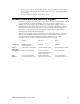
Table 2-2 DTE Modem requiring a null modem cable to DTE i.LON 10 Adapter Connection (DB-9 to DB-9) Modem Signal Name Cable DB-9 Male Null Modem Cable DB9 Femal e i.LON 10 (DTE) DB-9 Male DCD Pin 1 Pin 1-1 Pin 1 DCD—Pin 1 RxD Pin 3 Pin 2-3 Pin 2 RxD—Pin 2 TxD Pin 2 Pin 3-2 Pin 3 TxD—Pin 3 DTR Pin 4 Pin 4-6 Pin 4 DTR—Pin4 GND Pin 5 Pin 5-5 Pin 5 GND—Pin 5 DSR Pin 6 Pin 6-4 Pin 6 DSR—Pin 6 RTS Pin 7 Pin 7-8 Pin 7 RTS—Pin 7 CTS Pin 8 Pin 8-7 Pin 8 CTS—Pin 8 i.
Table 2-4 DTE Modem requiring a null modem cable to i.LON 10 Adapter Connection (DB-25 to DB-9) Modem Signal Name Cable DB-25 Male Cable DB9 Female i.LON 10 (DTE) DB-9 Male DCD Pin 8 Pin 1 DCD—Pin 1 TxD Pin 3 Pin 2 RxD—Pin 2 RxD Pin 2 Pin 3 TxD—Pin 3 DTR Pin 20 Pin 4 DTR—Pin4 GND Pin 7 Pin 5 GND—Pin 5 DSR Pin 6 Pin 6 DSR—Pin 6 RTS Pin 4 Pin 7 RTS—Pin 7 CTS Pin 5 Pin 8 CTS—Pin 8 i.LON 10 modem DB-25 male end Null Modem DB-9 male end Mounting the i.
Be sure the heads of screws are protruding slightly from the mounting surface. 3. Slide the i.LON 10 Ethernet adapter onto the screws. You may need to adjust the screws into or out of the wall slightly to assure a secure mounting. i.LON 10 Hardware Specifications Operating Input Voltage Power line: 12.
IC Compliance Statement – Class B This Class B digital apparatus meets the requirements of the Canadian Interference-Causing Equipment Regulations of ICES-003. VCCI Compliance Statement – Class B ITE This is a Class B product based on the standard of the Voluntary Control Council for Interference (VCCI) for information technology equipment. If this equipment is used near a radio or television receiver in a domestic environment, it may cause radio interference.
3 Using the i.LON 10 Ethernet Adapter with a 10BaseT Connection This chapter discusses how to configure the i.LON 10 Ethernet Adapter’s General Setup web page to facilitate communications between the LONWORKS network and the LNS Server using TCP/IP. i.
The i.LON 10 Ethernet Adapter General Configuration Page You can access the i.LON 10 Ethernet Adapter’s General setup page by pointing your browser to 192.168.1.222 and clicking the Setup link. If you are unable to access the i.LON 10 Ethernet Adapter’s web pages, ensure that: • The PC is on the same subnet as the i.LON 10 Ethernet Adapter. By default, the IP address of the i.LON 10 Ethernet Adapter is 192.168.1.222.
The setup page has the following fields: Hostname The TCP/IP host name of the i.LON 10 Ethernet Adapter. This name will be converted to all lower case by the firmware. When the i.LON 10 Ethernet Adapter establishes a connection with an LNS server it provides its fully qualified host/domain name so the LNS server knows which LONWORKS database to open. By default, the i.LON 10 Ethernet Adapter’s host name is ilon10. The i.LON 10 Ethernet Adapter must be reset for change in this value to take effect.
Server is not set. By default, this value is 0.0.0.0. Primary/Secondary DNS Server The primary and secondary DNS Servers used to resolve LNS Server names if Obtain IP address from DHCP Server is not set. If DNS servers are specified both here and by the DHCP server, the DNS server specified by DHCP will be used. LNS Server 1/2/3 Up to three LNS Server names or IP addresses in the form : or : (for example, you can specify 123.2.34.1:1628 or mylns.
Delay Time Between Two Retries This option is not supported for LNS 3, Service Pack 8, Update 1, and earlier. This option is only available if Notify xDriver Each Time IP Address Changes is checked. If the i.LON 10 attempts to inform the xDriver of an IP address change and is not successful, this is the amount of time before another attempt is made. Maximum Retry Time This option is not supported for LNS 3, Service Pack 8, Update 1, and earlier.
3-6 Using i.
4 Using the i.LON 10 Ethernet Adapter With a Modem This chapter describes how to connect a modem to the i.LON 10 Ethernet adapter and how to configure the PPP web page to allow the i.LON 10 to dial-out, accept incoming calls, and respond to shoulder-tap. i.
Connecting The i.LON 10 Ethernet Adapter to a Modem You can connect the i.LON 10 Ethernet Adapter to an analog, GSM, or ISDN modem using a standard DB-9 – DB-25 straight though modem cable. You must use a straight through modem cable to connect the i.LON 10 to the Modem. A crossover cable will not work. In order to for a modem to communicate with the i.LON 10, it must support all of the following signals: Tx, Rx, GND, RTS, CTS, DSR, DTR and CD.
This Web page contains the following options: Serial Port Baud Rate The speed of communications on the DB-9 serial port. The i.LON 10 Ethernet Adapter supports rates of 9600 bps, 19200 bps, 38400 bps, and 56700 bps. The serial bit rate should equal the bit rate of the attached modem. Local IP Address for Incoming Calls Set the IP address that will be assigned to incoming calls by the i.LON 100 server. By default, this is the IP address of the i.LON 10 incremented by one (e.g. if the IP address of the i.
made to the first profile, the second will be tried. The i.LON 10 will alternate between profiles until a connection is established or until the number of retries specified by Number of Retries to Use when Attempting Outbound PPP Connection Attempts on the Security Configuration Web page has been reached. Each profile contains the following options: Username The username to be used by the i.LON 10 Ethernet Adapter when connecting to an ISP. This name can be up to 63 characters.
Setting this value to 0 disables the idle timeout (i.e. the connection will stay open indefinitely). Modem Init String The initialization string sent to the modem before each connection attempt. Use this field to insure that the modem’s baud rate matches the value set in Serial Port Baud Rate. The Modem Init String for Profile 1 is sent on the serial port each time the i.LON 10 is reset. You do not need to enter “AT” before each member of the init string (i.e.
If this checkbox is cleared, this information will be set by the ISP. Submit Click to close this page, write the configuration changes to FLASH memory, and reset the i.LON 10 Ethernet Adapter. Configuration changes will take effect upon reboot. Configuring the i.LON 10 Ethernet Adapter for Dial-out The i.LON 10 Ethernet Adapter can be configured to dial-out when it needs to form an uplink communication with the LNS Server. To configure the i.
Troubleshooting Dial-out Problems If you are having trouble getting the i.LON 10 Ethernet Adapter to connect to an ISP, perform the following tests: Test the Modem To test the modem, follow these steps: 1. Connect the modem to your computer’s serial port using the straight-through modem cable used to connect the i.LON 10 to the modem. 2. Open HyperTerminal. Assure that the scroll lock is turned off on your computer (if it is on, press the button to turn it off).
ii. Type “AT” in capital letters and press . The modem should respond with “OK”. If the modem does not respond, repeat this step several times. If you cannot get a response, verify that the modem is turned on. iii. If you still get no response, watch the LEDs on the modem when you enter ‘AT”. If they do not flicker, the modem is not responding the command. This could be due to any of the following: • Wrong type of modem cable being used. Confirm that you are using a straight through cable.
1. On the computer attached to the modem, dial the ISP. In HyperTerminal, type “ATDT 555-1234” (replace 555-1234 with the phone number supplied by your ISP for POP connections. Be sure to include an prefixes needed to get an outside line. A comma may be used to force a short pause (e.g. “ATDT 9,555-1234”). You should hear a dial tone, then dialing, and a high-pitched whistling when the ISP’s modem picks up. You may or may not see anything on your HyperTerminal display (this varies by ISP).
the host. This should force the i.LON 10 to dial-out. Watch the modem LEDs for activity and listen for dial tone, ringing, and connection: • If the modem LEDs do not flash, the i.LON 10 is probably not communicating with the modem. • If the LEDs flash, but the modem doesn’t dial: i. Set Modem Init String on the PPP Configuration Web page to “&F”. This will reset the modem to its factory defaults. ii. Check that the RS-232 line speed is the same as you used when testing the modem with the computer. iii.
modem cable used to connect the i.LON 10 to the modem. 2. Open HyperTerminal. Assure that the scroll lock is turned off on your computer (if it is on, press the button to turn it off). In HyperTerminal, set the Bits Per Second to the same rate as used to communicate with the i.LON 10. Set Data Bits to 8, Parity to None, Stop Bits to 1, and Flow Control to Hardware, as shown in the following figure: 3. In HyperTerminal, turn on Echo. To do this, follow these steps: i.
• Wrong type of modem cable being used. Confirm that you are using a straight through cable. • Faulty modem cable being used. Try a different straight through cable. • You are connected to a different serial port than the one provided to HyperTerminal. Many computers have multiple serial ports (COM1, COM2, etc.), and often COM1 is used for the internal modem. Try switching HyperTerminal to COM2, COM3, etc. • Serial port is malfunctioning. Try connecting to a different serial port.
4. Verify that the user name and password set using Dial Up and Networking Connections on the computer matches the user name and password set on the PPP Setup Web page of the i.LON 10. 5. Assure that LCP Extensions is unchecked in the Windows PPP Settings dialog. You can open this dialog by following these steps: i. Open the Windows dial-up connection used to dial the i.LON 10. ii. Select the Networking tab. iii. Click the Settings button. 6.
4. Ensure that the Allow PPP Dial-back (Shoulder Tap) checkbox is set. You must clear the Allow and Authenticate Incoming PPP Connections checkbox to do this. 5. Set Respond to Shoulder Tap after Rings. If the i.LON 10 receives a call of at least this many rings, once the caller has hung up, the i.LON 10 will initiate a dial-out session. 6. Ensure that the Enable Outbound PPP Calls checkbox is set. 7. Set Number of Retries to Use When Attempting Outbound PPP Connection Attempts. 8. Click Submit. 9.
Using GSM/GPRS Modems with the i.LON 10 Ethernet Adapter In order for a GSM or GPRS modem to communicate with the i.LON 10, it must support all of the following signals: Tx, Rx, GND, RTS, CTS, DSR, DTR and CD. Check with your service provider to confirm that the modem you want to use supports these signals. GSM/GPRS Service Providers Tested with the i.LON 10 Ethernet Adapter The following table lists the GSM/GPRS service providers that have been tested with the i.
4-16 Using i.
5 i.LON 10 Ethernet Adapter Security This chapter describes the security of the i.LON 10 Ethernet Adapter. i.
i.LON 10 Ethernet Adapter Security The i.LON 10 Ethernet Adapter can institute a number of measures to make itself as secure as possible: • MD5 Authentication. The i.LON 10 Ethernet Adapter provides the option of using MD5 Authentication with all communications between it and the LNS Server, requiring a 16 byte authentication key. See i.LON 10 Ethernet Adapter Security Web Page in Chapter 5 for more information. • Security Web Page. The i.
your computer must be able to communicate on the 192.168.1.x subnet. This can be accomplished in one of the following ways: • Manually change your computer’s IP address to 192.168.1.x (where x is any value from 2-255). • Open a DOS command line window and enter the following command: route add 192.168.1.0 mask 255.255.255.0 When in security access mode you can access the Security Web page and the other features listed above until the i.LON 10 is reset.
Allow HTTP Access Set this option to allow users to access the i.LON 10 web pages with the exception of the Firmware Page and the Security Page (both of which can only be accessed after a security access reset). If set, enter a Username and Password that will grant access. The Username and Password may contain up to 16 alphanumeric characters; they are case sensitive. By default, the Username and Password are set to ilon. If this option is not checked, you will not be able to view any of the i.
out connection if an attempt to establish a Ethernet connection fails. Auto Redial on ISP Disconnect Set this checkbox to have the i.LON 10 Ethernet Adapter automatically attempt to reestablish a dial-out connection if the connection is terminated by the ISP. Enable Outbound PPP Calls Set this checkbox to allow the i.LON 10 Ethernet Adapter to establish PPP connections. If this checkbox is set, set Number of Retries to Use When Attempting Outbound PPP Connection Attempts.
information in the correct order. This option is enabled by default, but should be disabled if you do not need to dial into the i.LON 10 in the field. Note: If this option is enabled, the Enable Ethernet Connections option should be disabled. The i.LON 10 does not support simultaneous Ethernet and PPP connections. Raw MD5 Authentication Key/Text Shared Secret A key or phrase used to authenticate communication between the i.LON 10 Ethernet adapter and the LNS Server.
• Enable TFTP – Disable this option unless you will need to update the i.LON 10 user web page in the field. If you leave this option enabled, be sure to change the default Password. • Allow and Authenticate Incoming PPP Connections – Disable this option unless you will be dialing into your i.LON 10 in the field. If you leave this option enabled, be sure to change the default Username and Password. If you will not be dialing directly into the i.
5-8 i.
6 Uploading i.LON Network Adapter Firmware and the User Web Page This chapter describes how to use a TFTP application to upload upgrades to the i.LON 10 Ethernet Adapter Firmware and the User Web Page. i.
Uploading i.LON 10 Ethernet Adapter Firmware Firmware upgrades for the i.LON 10 Ethernet Adapter may become available on the Echelon i.LON web page (www.echelon.com/ilon). You can check the current version of the firmware on the i.LON 10 device’s status web page as described in Chapter 7. To upload a firmware upgrade to the i.LON 10 Ethernet Adapter hardware, follow these steps: 1. Perform a security access reset (see Performing a Security Access Reset in Chapter 6). Firmware can only be loaded when the i.
This command must be executed within 4 minutes of clicking Begin Firmware Upgrade Sequence. Once the upgrade has completed, the Service LED will turn off, indicating the i.LON 10 Ethernet Adapter has resumed normal operation. Once you have updated the firmware, you may experience trouble accessing the Setup web page. This is due to Internet Explorer attempting to use a cached version of the setup web page. If this happens, delete your cached web pages (i.e.
Using the Microsoft® TFTP Client You can use Microsoft’s TFTP client from a Windows command line to upload a user web page. This can be done using the following format: TFTP -i host PUT source password The –i flag specifies binary image transfer mode, and should always be used when uploading a user web page to the i.LON 10 Ethernet Adapter. For example, to upload the file ETH0006.hex from c:\temp to an i.LON 10 with an IP address of 192.168.1.
7 i.LON 10 Ethernet Adapter Diagnostics This chapter describes the diagnostic information from the i.LON 10 Ethernet Adapter. i.
i.LON 10 Diagnostics The i.LON 10 Ethernet Adapter provides two web pages that display diagnostic information, the Status page and the Event Log page. Viewing i.LON 10 Ethernet Adapter Status You can check the status of the i.LON 10 Ethernet Adapter by clicking the Status link from the Setup web page. The Status page appears as shown in the following figure: This web page displays the status of the i.LON 10. This information can be used to troubleshoot communication problems or to verify settings.
domain varies and can be set by a network tool such as the LonMaker tool. Subnet/Node The LONWORKS address associated with the i.LON 10 Ethernet Adapter. A network tool such as the LonMaker tool sets this value. Ethernet MAC The Ethernet MAC address of the i.LON 10 Ethernet Adapter. Transmission Errors The number of CRC errors on the FT or LP channel detected during packet reception since the last reset. Transmission Timeouts The number of times since the last reset that the i.
The following events are logged in this web page: Message =====iLON-10 Started===== 7-4 Description The i.LON 10 Ethernet Adapter unit has been started in one of the following ways: • by plugging in the power adapter. • by saving a new configuration. ===== i.LON-10 Started in SECURE MODE ===== This message indicates the unit was started in SECURE MODE (holding the Service Pin in for 10 seconds as the unit is powered on). ===== i.
Message Description internal Neuron Chip for at least 1 minute after startup. HTTP: host at failed to authenticate properly This message indicates that an attempt was made from to access the configuration web pages, but that attempt was not successful. Configuration changes saved - restarting system This message indicates that a configuration change was saved.
7-6 Message IDENT_UNKNOWN from LNS server Description server has sent an XDRIVER_ACK message with reason code set to IDENT_UNKNOWN. Port #n: Received SERVICE_UNAVAIL from LNS server This message indicates that the LNS server has sent an XDRIVER_ACK message with reason code set to SERVICE_UNAVAIL. Port #n: Received SERVICE_REFUSE from LNS server This message indicates that the LNS server has sent an XDRIVER_ACK message with reason code set to SERVICE_REFUSE.
Message Description Port #n: could not write Configuration data after xDriver INCAUTH command This message indicates that the new secret key and configuration were not properly saved. This message should never be seen. If it is, the unit should probably be returned for service (ie, a new flash chip installed.) Port #n: Listening for connection on tcp port The i.LON 10 Ethernet Adapter is setting up a socket to listen for LNS Servers on the given port number.
Message Port #n: Listening for connections on tcp port pppp was not possible (Error #nn) Description This message indicates that a TCP connection was not possible due to error nn. Errors are listed below: Port #n: Connection attempt to ###.###.###.###:##### was not possible (Error #nn) 1 - the i/o request has been scheduled but not completed Port #n: Incoming connection on tcp port from ###.###.###.
Message Description Port #n: Session aborted with LNS server This message indicates that the current LNS server shutdown abruptly without first receiving a TERM command. Port #n: sessionid/sequence number invalid on incoming Xdriver packet This message indicates that the expected sessionid or sequence number does not match the data in the incoming Xdriver packet.
Message 7-10 Description authoritative answer. DNS: "" does not exist (authoritative answer)" This message indicates that the DNS server responded to the query but has no entry for the given hostname. The DNS server gave this response as an authoritative answer. DNS: "" resolved to ()" This message indicates that the DNS server responded to the query with an IP address. The fully-qualified name is given in parenthesis.
Message Description to dial out. AUTOPPP: Incoming call accepted This message indicates that the i.LON 10 has received the configured number of rings and has issued an "ATA" command to the modem to answer the call. AUTOPPP: Two successive attempts to 'xxx-xxxx' resulted in answer but no carrier (possibly voice) These messages indicate that there were two consecutive voice answers on the phone number dialed. No further attempts on this number are permitted. These two messages will appear together.
Message Description parenthesis in the same message. This message may include a reason in parenthesis, described below. The previous three messages, may include one of the following reasons: (ISP_specific_message) – A message sent by the ISP and passed on to the i.LON 10 system log. Contact your ISP for more information on this message. (no reply to echo requests) – PPP echo requests do not result in a response from the PPP peer. (carrier lost) – The carrier has been lost.
Message received Description call has been detected and answered. PPP: Network connection established This message indicates that a network connection has been established through PPP. The IP address obtained will appear in parenthesis next to the message. PPP: Incoming connection authentication succeeded This message indicates that an incoming call has been authenticated and a connection has been established.
A series of tests and results will display as shown above. When the LED #1 and LED #2 tests occur, the appropriate LED will flash so you can verify that it is functioning. Restoring Factory Defaults To reset the i.LON 10 Ethernet Adapter to its factory defaults, click the Factory Defaults link on the i.LON 10 Web Page. This link is only available after a security access reset. The following web page opens: To restore factory defaults, click Yes. A confirmation page with a Submit button will appear.
that if your PC is not on the 192.168.1.x subnet, you may have to change the IP settings of your PC to communicate with the i.LON 10 Ethernet Adapter or use the route command described in the Quick Start and in Performing a Security Access Reset. Rebooting the i.LON 10 Ethernet Adapter To reboot the i.LON 10 Ethernet Adapter, click the Reboot link on the i.LON 10 Web page. The following Web page opens: To reboot the i.LON 10 Ethernet Adapter, click Reboot Now.
7-16 i.
8 Establishing an Uplink Connection Through the i.LON 10 Ethernet Adapter This chapter describes how to establish an uplink connection through the i.LON 10 Ethernet Adapter. i.
Uplink Connections An uplink connection is a connection initiated by a device on the network attempting to communicate with the LNS Server on the other side of the i.LON 10 adapter. This occurs when a device sends data to the LNS Server without the data being requested, such as when one or more network variables are bound to the host (see the LNS Programmer’s Guide, the LonMaker User’s Guide, and the LNS for Windows Programmer’s Guide, xDriver Supplement for more information).
4. Start an LNS application that listens for xDriver Broker events. See the LNS for Windows Programmer’s Guide, xDriver Supplement for more information. i.
8-4 Establishing an Uplink Connection Through the i.
Appendix A Using the Webconvert Utility The Webconvert utility is a program that is used to convert web pages into the Intel hex format (.hex extension) that can be downloaded to the i.LON 10 Ethernet Adapter. This appendix contains instructions for using the Webconvert utility. See Uploading a User Web Page in Chapter 6 for more information. i.
The Webconvert Utility Webconvert allows the user to select a base directory and location to store the converted file. Webconvert traverses the base directory and all sub-directories. The base directory path is removed from the converted filename or sub-directory (e.g., C:\BaseDir\index.htm becomes index.htm and C:\BaseDir\SubDir\pic1.jpg becomes SubDir/pic1.jpg). Webconvert handles the following file extensions .au, .jpeg, .jpg, .gif, .htm, .html, .mov, .mp3, .mpeg, .mpg, .png, .ps, .swf, .tif, .tiff, .
5. After the conversion has been completed, the log box shows how many files have been converted, the total converted file size, what files have been converted, and any errors that may have occurred (see Webconvert Utility Log Messages, below), as shown in the following figure: 6. Once you are finished converting folders, click Exit to quit the Webconvert utility. See Uploading a User Web Page in Chapter 6 for information on using a TFTP client to upload a converted Web page to an i.
Total Converted Data size is greater than 32 Kb A-4 The i.LON 10 Ethernet Adapter has a maximum size of 32 kB to store web pages. If the size of the files in the folder you selected is greater than 32 kB, this message will appear. The conversion will be cancelled.
Appendix B The xDriver Software This appendix describes how to install and configure the xDriver software to allow the i.LON 10 Ethernet Adapter to communicate with the LNS Server. i.
Download and Install the OpenLDV Driver The OpenLDV driver provides LONWORKS tools and applications with a unified Windows interface for sending and receiving LonTalk messages on your i.LON 10 Ethernet Adapter. You can obtain OpenLDV from the download section of the Echelon website at www.echelon.com. Use the OpenLDV ReadMe File, also available at the download site, for an overview of the driver and installation instructions.
2. The control panel applet lists the LNS network interface name of all the i.LON 10s that have been added to the Registry below the Default item. In the figure above three i.LON 10s have been added to the Windows Registry. Default represents the Default xDriver Profile. This is the set of configuration parameters that determines how the default xDriver will manage connections to your i.LON 10s.
4. Click OK. This opens the tab shown in the following figure: 5. Configure the fields on the General tab. The following table describes these fields. Field Hostname Description Maximum Length: 63 chars Legal Chars: A-Z, a-z, “-“, 0-9 Comments: Enter the TCP/IP hostname of the i.LON 10. xDriver will use the hostname to connect to the i.LON 10. DNS Suffix Maximum Length: 63 chars Legal Chars: A-Z, a-z, “-“, 0-9,”.” Comments: Enter the name of the IP domain on which the i.LON 10 is installed.
7. Configure the fields on the Address/Port tab. The following table describes these fields. Field Description i.Lon is listening on port: Default Value: 1628 Use Static IP Address Comments: Click the Use Static IP Address button to manually enter the IP address of the i.LON 10. You must enter an IP address in the form x.x.x.x, where x is an integer in the range 0-255. Range: 1-65,535 Comments: Enter the TCP port number the i.LON 10 is using to listen for incoming connections from the LNS server.
8. You can choose to authenticate connections to this i.LON 10 using the MD5 authentication key or the text secret phrase configured into the i.LON 10. Using an MD5 authentication key or text secret phrase prevents the LNS Server and the i.LON 10 from responding to unauthorized messages during an xDriver session. NOTE: This authentication key is not the same as the authentication key used within the LONWORKS network. To use the MD5 authentication key, click the Use MD5 Key button.