
Instruction Manual
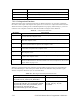
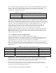
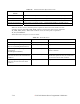
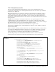

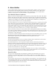
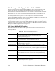

Table 28 Alarm Generator Hysteresis Levels
Offset Limit Causing
Alarm
Alarm Cleared When...
<UCPThighLimit1Offset>
Input Value<=Comp Value+ UCPThighLimit1Offset – SCPThysHigh1
<UCPThighLimit2Offset>
Input Value<=Comp Value+ UCPThighLimit2Offset – SCPThysHigh2
<UCPTlowLimit1Offset>
Input Value>= Compare Value – UCPTlowLimit1Offset + SCPThysLow1
<UCPTlowLimit2Offset>
Input Value>= Compare Value – UCPTlowLimit2Offset + SCPThysLow2
When an alarm is cleared, the data point is updated to the next lowest alarm level. For
example, when an AL_LOW_LMT_ALM_2 alarm is cleared, the data point is updated to
AL_LOW_LMT_ALM_1. When that condition clears, the data point is updated to
AL_NO_CONDITION.
Table 29 describes this process in more detail.
Table 29 Alarm Statuses
Event Input Data Point Status Comments
Value of input data point is normal. AL_NO_CONDITION No alarm condition.
Value of input data point goes above
first level (UCPThighLimit1Offset).
AL_HIGH_LMT_ALM1 Updated to the first alarm condition.
Value of input data point goes above
second level
(UCPThighLimit2Offset).
AL_HIGH_LMT_ALM2 Updated to the second, and more severe,
alarm condition.
Value of input data point goes below
hysteresis level for the second alarm
condition.
AL_HIGH_LMT_ALM1 Updated back to the first alarm condition,
as the data point has not yet reached the
hysteresis level for that condition.
Value of input data point goes below
hysterisis level for the first alarm
condition.
AL_NO_CONDITION Updated back to normal status.
i.LON 100 Internet Server Program7-14 mer’s Reference