
Instruction Manual


i.LON 100 Internet Server Programmer’s Reference
Property Description
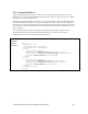
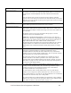
<ActiveAlarm>
If the input data point is updated and matches the conditions defined by
any of the active alarm condition sets, it is considered an active alarm. In
this case, the Alarm Notifier will use its active destinations. You can
create as many active alarm condition sets as you want per Alarm
Notifier.
The active alarm condition sets for an Alarm Notifier are signified by a
list of <ActiveAlarm> elements. For a description of the properties that
must be defined within each <ActiveAlarm> element, see Active and
Passive Alarm Condition Sets on page 8-15.
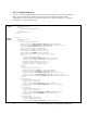
<PassiveAlarm>
If the input data point is updated and matches the conditions defined by
any of the passive alarm condition sets, it is considered a passive alarm.
In this case, the Alarm Notifier will use its passive destinations. You can
create as many passive alarm condition sets as you want per Alarm
Notifier.
The passive alarm condition sets for an Alarm Notifier are signified by a
list of <PassiveAlarm> elements. For a description of the properties that
must be defined within each <PassiveAlarm> element, see Active and
Passive Alarm Condition Sets on page 8-15.
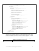
<AlarmDest>
Each <AlarmDest> element defines a group of active and passive alarm
destinations the Alarm Notifier will use. The active destinations are
signified by a list of <ActiveDest> child elements within the
<AlarmDest> element. The passive destinations are signified by a list of
<PassiveDest> child elements within the <AlarmDest> element. For a
description of the properties that must be defined within each of these
child elements, see Active and Passive Alarm Destinations on page 8-16.
Each <AlarmDest> element also contains 2 global elements: its index
number (UCPTindex), and its enable data point (UCPTdestEnable). The
<UCPTdestEnable> property is optional. You can reference a
SNVT_Switch data point by its name (UCPTpointName) here. The
<AlarmDest> will then be enabled when that data point is set to 100.0 1,
or disabled if that data point is set to 0.0 0. You could set this data point
with a L
ONWORKS switch, or with the Event Scheduler application.
This allows you to enable or disable an Alarm Notifier’s destination sets
under different circumstances.
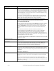
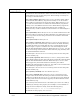
8.2.1.2.1 Input Data Points
The following table describes the properties that you must define within each <Point>
element. As described in the previous section, each <Point> element defines an input data
point for the Alarm Notifier. Each time any of the input data points are updated, the Alarm
Notifier will check if it has reached an alarm condition.
If an input data point is updated and meets an active or passive alarm condition, then an
alarm notification will be loggeed, and the applicable passive or active alarm destinations
will be used.
8-10