i.
Echelon, LON, LONWORKS, LonTalk, LonBuilder, LonManager, Neuron, 3120, 3150, LONMARK, NodeBuilder, and the Echelon logo are trademarks of Echelon Corporation registered in the United States and other countries. LonMaker and i.LON are trademarks of Echelon Corporation.
Contents 1 Introduction 1 2 Hardware and Software Installation 7 3 Working with Web Pages 25 4 Troubleshooting 31 Contents of the i.LON 1000 Internet Server Starter Kit PC Requirements Software Installation Getting More Information and Technical Support Introduction to the i.LON 1000Internet Server Hardware Installation Hardware Step-by-Step Installation Software Step by Step Installation Transferring Web Pages to the i.LON 1000 using FTP Viewing the Web Pages in a Browser demo1page1.
1 Introduction Welcome to the i.LON 1000 Internet Server Starter Kit. This ® kit builds upon the Model 37400 LON WORKS System Starter Kit by supplying you with everything you need to add web access to your control system. i.
Introduction The i.LON 1000 Internet Server (Echelon Model 72001 or 72002) adds web-based monitoring and control to the LonPoint™ applications described in the Getting Started with the LONWORKS System Starter Kit document. Once the examples described below are completed and you understand the basic principles of web-based monitoring and control, you can use the i.
page3getvalues.htm, page3main.htm HTML support files used by demo1page3.htm ash_bottom.jpg, ash_left.jpg, ash_right.jpg, ash_top.jpg, hvac_anim.gif, hvac_bg.gif, hvac_off.gif, pid_bg.gif, pid_slider.gif, slider_bg.gif, slider_knob.gif, temp_bg.gif, temp_slider.gif Graphic support files used by demo1page3.htm PC Requirements The PC requirements for this starter kit are identical to the requirements for the Model 37400 LONWORKS System Starter Kit. The same PC should be used to execute both kits.
Notice:: The support programs and the information in the following table are subject to change. See the Echelon Services home page at www.echelon.com/Services for a description of the current offerings and support contacts.
Power LED Figure 1.1 i.LON 1000 Front Panel The i.LON 1000 offers unparalleled performance and reliability. Certified under the Cisco NetWorks™ program, the i.LON 1000 integrates Echelon's control networking and routing expertise together with Cisco's Network Foundation Technologies. The result is a layer 3 LONWORKS router that offers very high packet throughput for demanding process control, building automation, utility, transportation, and telecommunications applications.
The i.LON 1000’s built-in Web server allows control information (such as network variables representing temperature, occupancy, speed, etcetera) to be accessed easily through a web browser. This feature provides access to LONWORKS monitoring and control data from anywhere without the need for special software tools, over LANs, WANs, or the Internet.
2 Hardware and Software Installation This chapter provides information for installing the i.LON 1000 Internet Server hardware and software with the L ON WORKS System Starter Kit. i.
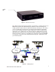
Hardware Installation Recall the LonPoint hardware installation described on pages 2-15 and 2-16 of Getting Started with the LONWORKS System Starter Kit. You will expand the hardware installation to include the i.LON 1000 Internet Server. The final topology is shown in figure 2.1. A picture of the actual components is shown in figure 2.2 Ethernet 10BaseT Hub 10BaseT Netscape or Internet Explorer i.LON 1000 LonMaker™ for Windows FTT-10 DIO AO AI Figure 2.
Hardware Step-by-Step Installation 1 Verify that the PC is connected to the LONWORKS network and that you can run LonMaker for Windows and the HMI examples as documented in Chapter 3 of Getting Started with the LONWORKS System Starter Kit. 2 Verify that TCP/IP networking is installed and running on the PC. (See your network administrator or the Windows TCP/IP networking documentation for information on setting up Windows TCP/IP networking.) 3 Connect both the PC and the i.
Software Step-by-Step Installation Follow these steps to install your software. 1 Connect to the i.LON 1000 console application using Hyperterminal. a) Using the null-modem cable (not pictured in the above diagrams) that shipped with the i.LON 1000, connect an available COM port on your PC to the i.LON 1000 console port. Be sure that a modem driver, palm organizer driver, or other serial device is not already using the COM port you choose on your PC. b) Run Hyperterminal on your PC.
e) 2 Next, Hyperterminal will prompt you for the RS-232 (COM1 or COM2) communication parameters. The i.LON 1000 communicates at 9600bps, using 8 bit data, 1 stop bit, and no parity. No flow control is necessary. Set the parameters in the hyperterminal communication property dialog accordingly. Initialize the i.LON 1000’s IP address, subnet mask, and default gateway. a) Press the PC’s Enter key twice. The i.LON 1000 console application should respond with the ILON> prompt.
c) Get a static IP address, subnetmask, and default gateway address from your TCP/IP system administrator. Important: It is critical that you select an IP addressing scheme that is compatible with your local TCP/IP network. Check with your system administrator; do not use an IP address until you have confirmation that it will not adversely affect your local network. The example addresses provided below are probably incorrect for your local network.
Note: This is a good time to test TCP/IP communication between the PC and the i.LON 1000 by pinging the i.LON 1000 from the PC, and by pinging the PC from the i.LON 1000. Open the Windows Start menu, point to Programs, and choose the MS-DOS Prompt to open a DOS box. Type: ping 10.1.0.170. From the i.LON 1000 console application type: ping . See your TCP/IP network administrator for information on how to use the ping command.
c) Select the device shape (titled Device) from the LonMaker Basic Shapes stencil and drag it to the LonMaker drawing. Place the new device just to the right of the DIO shape. The LonMaker tool will ask for a device name to associate with the device shape you just dropped. Set the device name to “iLON1” and select the Commission Device checkbox. Click Next. d) The next window asks you where the LonMaker tool should find information about the i.LON 1000 device. Because the i.
e) The LonMaker tool allows you to select which channel the i.LON 1000 will be connected to. Our example network has only a single channel, the TP/FT-10 channel (named Channel 1), which the LonMaker tool automatically selects for the i.LON 1000. Click Next to accept the selection. f) LONWORKS devices can be assigned properties that may be useful in larger networks.
g) Click Next to use the service pin method of device identification. This is the easiest way to get an i.LON 1000 Neuron ID into the LonMaker tool if the LonMaker PC is actually attached to the LONWORKS network, like it is in this example. h) It is not necessary to load the i.LON 1000’s application image because the i.LON 1000 comes preloaded from the factory. Leave the Load Application Image checkbox cleared, and click Next. 16 i.
i) Specify Online as the initial state of the i.LON 1000, click Next. j) The LonMaker prompts you to press the service pin on the i.LON 1000. Using a ballpoint pen or similar object, press the recessed button marked “Service” on the back of the i.LON 1000. This causes the i.LON 1000 to send a service pin message on the LONWORKS network. The LonMaker tool captures this message and commissions the i.LON 1000. Your LonMaker drawing should now look like figure 2.4 Figure 2.
4 The next step is to connect input and output network variables representing the points to display in your web page to the i.LON 1000. Recall the HMI application example in Chapter 3 of Getting Started with the LONWORKS System Starter Kit. In that example, an HMI application was created that monitored 4 points.
a) Drag a Functional Block shape from the LonMaker Basic stencil to the LonMaker drawing. The LonMaker tool will prompt you with a dialog asking you to select a functional block from a particular device. Select the ilon device from the Device list. Select Virtual Functional Block from the Functional Block list. Click Next. b) The LonMaker tool will now prompt you to name this functional block. Choose a descriptive name such as iLON WebNode. Click Finish. i.
Your LonMaker drawing now displays the functional block, but it has no network variables, and is not connected to anything. You must now add the network variables for the functional block. A powerful feature of using the LonMaker tools and i.LON 1000 together is the ability to define the network variables dynamically. In this way, you can optimize the use of network variables on the i.LON 1000 and select the exact network variable type for each of your connections.
d) Click the Create NV button. This brings up a dialog that allows you to define the network variable you want to create. Enter nviTempSensor as the name, and click Browse. Be careful when typing the network variable name. This name must be exactly the same as the name referenced in the i.LON 1000 web page to be created later. Names are case sensitive. e) The Select Object dialog allows you to navigate the LNS object hierarchy to the point you want to monitor.
f) The string A/AI- 1/Temperature Sensor/Analog string will now be displayed in the Source Network Variable section of the Create Network Variable window. g) Click OK. This instructs the LonMaker tool to create a network variable on the i.LON 1000 that is a complement to the A/AI- 1/Temperature Sensor/Analog network variable. See the LonMaker for Windows Integration Tool User’s Guide for more information on dynamic network variable creation and complement network variables.
i) The LonMaker tool places that network variable on the functional block, providing a connection point. j) Repeat the process outlined in steps 4c through 4i. Create two more input network variables and an output network variable on the functional block.
k) Drag the Connector shape from the LonMaker Basic Shapes stencil onto the LonMaker drawing. Use this tool to connect the newly created network variables to other points in the system, as shown in figure 2.5 l) Right click the DIO hardware device shape. Select commission from the shortcut menu. m) Right click the AI-1 hardware device shape. Select commission from the shortcut menu. n) Right click the AO-1 hardware device shape. Select commission from the shortcut menu.
3 Working with Web Pages This chapter provides information on web pages. It includes information for creating, transferring, and viewing these pages. i.
Transferring Web Pages to the i.LON 1000 using FTP Following the steps in Chapters 1 and 2, you created a fully functional LONWORKS network. As network variables change, the i.LON 1000 receives updates for each connection defined in step 4k above. The next step is to create a web page that allows those network variable values to be viewed in a standard web browser. a) The following three sample web pages display the network variables defined on the virtual functional block created in step 4: demo1page1.
150 Opening BINARY mode data connection 226 Transfer complete ftp: nnn bytes sent in 0.00Seconds nnn.00Kbytes/sec. ftp> put demo1page2.htm 200 Port set okay 150 Opening BINARY mode data connection 226 Transfer complete ftp: nnn bytes sent in 0.00Seconds nnn.00Kbytes/sec. ftp>quit 221 Bye...see you later C:\> The i.LON 1000’s console application allows you to browse the i.LON 1000’s flash disk using the DIR and CD commands. Using the console application, verify that the files ended up where you expected.
demo1page1.htm This page shows how to create an HTML page that reads input network variable values, and allows you to set an output network variable value. The idea here is to show the raw HTML necessary to transfer information, not create an attractive web page. Of Interest: Select SOURCE from the VIEW menu. Compare the source displayed by the browser to demo1page1.htm. Notice the server side substitution that occurred when the page was served. demo1page2.
demo1page3.htm This page is designed to show a sample user interface that can be built using JavaScript. The four “controls” on this page are in reality not controls at all; they are graphic images that are manipulated in the browser using JavaScript. The same effect can be accomplished using Java applets or ActiveX controls.
View demo1page3.htm using http://10.1.0.170/forms/demo1page3.htm. (Substitute your IP address) This page resembles the type of user interface that is often created with an expensive HMI tool. The entire page was created using JavaScript, HTML, and graphics; however, the illusion of actual controls exists. Using JavaScript Visit your local bookstore for a texts with more information on creative usage of JavaScript or visit the following web sites. http://devedge.netscape.
4 Troubleshooting This chapter provides suggestions for resolving problems you may have encountered in the previous chapters. i.
Resolving Problems To the newcomer, the LONWORKS system may appear to be just a device network. However, beyond the complete implementation of the ISO/OSI 7 layer networking model lies a very broad technology.
browser to connect to the i.LON 1000 to display web pages. Get help from your TCP/IP system administrator. The administrator is an expert on TCP/IP and knows how your TCP/IP network performs. The administrator also will know which values to use for IP address, subnet mask, etcetera. It is a common mistake to supply the wrong values. Remember that the values shown in Chapter 2 are to illustrate syntax only. Your network will require different values. d) Reset the i.
b) Open the network you just restored by clicking the Open Network button. Click through the LonMaker startup wizard. When prompted, be sure to select your network interface (PCC1 or PCLTA1) and set the network management mode to OnNet. Once open, the drawing should look like figure 4.1. Figure 4.1 Restored LonMaker Drawing Note that the i.LON 1000, the i.LON 1000’s functional block, and all connections are already made. You will notice red diagonal lines across each of your devices.
d) Exit the LonMaker tool. When prompted, select Yes to save your changes. 3 Ask your TCP/IP system administrator to help you verify that the files you transferred via FTP to the i.LON 1000 were transferred, and are now located in the correct directories. Remember that resetting the i.LON 1000 back-to-factory defaults did not delete any files that you may have already transferred to the i.LON 1000. It is helpful to use the Web Solution.