
User Manual


The LNS DDE Test example includes 5 application devices and a router, which
matches the hardware in a LonPoint Demo Kit. If you do not have LonPoint devices
to use with the examples, you can still open the examples in engineered mode to see
Excel and InTouch usage examples for the LNS DDE Server.
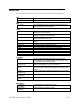
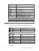
Following is a list of the 5 application devices defined in the LNS DDE Test example:
• AI- 1. A LonPoint AI-10 Analog Input Interface Module. Used to monitor a
simulated temperature and a temperature setpoint dial.
• AO- 1. A LonPoint AO-10 Analog Output Interface Module. Used to control a
simulated hot water valve actuator, and an analog meter monitoring the input to
the valve.
• DI- 1. A LonPoint DI-10 Digital Input Interface Module. Used to monitor 4 input
switches. Three of the switches are used to control the system mode, simulating
the output of a system mode generator. The fourth switch is used as a system
enable.
• DO- 1. A LonPoint DO-10 Digital Output Interface Module. Used to control 4
LEDs. Three of the LEDs are used to display the system mode. The fourth LED
is used to display the system enable status.
• SCH-1. A LonPoint SCH-10 Scheduler Module. This device is not used in the
example. Its operation is simulated by the mode simulator on the DI- 1 device.
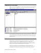
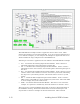
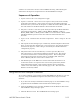
These five devices contain L
ONMARK objects that are shown as functional blocks on
the LonMaker drawing. Each functional block has network variable inputs and
outputs that are shown as triangles on the functional blocks. These network
2-12 Installing the LNS DDE Software