LonPoint Application and Plug-in Guide 9HUVLRQ & R U S R U D W L R Q $
(FKHORQ /21 /21:25.6 /RQ7DON 1HXURQ /210$5. /RQ3RLQW 6FKHGXOH 0DNHU 6FKHGXOH .HHSHU WKH /RQ8VHUV ORJR WKH (FKHORQ ORJR DQG WKH /210$5.
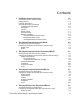
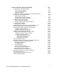
Contents 1 LonPoint System Overview Introduction to the LonPoint System Getting Started LonPoint Applications Terminology Used in this Manual Upstream and Downstream Heartbeats Throttle Default Values Override Values Network Variables Changing Network Variable Types Network Variable Formats Changing Network Variable Formats 2 The Digital Input Functional Block The Digital Input Functional Block Configuring the Digital Input with the LonPoint Plug-in Digital Input Status 3 The Digital Input/Counter Functio
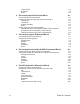
Lookup Tables Heartbeats Status 5-4 5-7 5-8 6 The Analog Input Functional Block 6-1 The Analog Input Functional Block Configuring an Analog Input with the LonPoint Plug-in Analog Input Translation Output Parameters Status Analog Input Gain and Current Settings Amps Measurement Type (2WIR and 4WIR Jumper Settings) Ohms Measurement Type (RES Jumper Setting) Volts Measurement Type (VOLT Jumper Setting) 7 The Analog Output Functional Block 7-1 The Analog Output Functional Block Configuring an Analog Outp
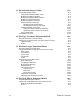
10 The Scheduler Functional Block Using the SCH-10 Scheduler Module SCH-10 Functional Blocks LonPoint Schedule Maker Types of Schedules Overview of the Supervisory Application Development Process Creating an Event Schedule Design Defining Daily Schedules Assigning Default Daily Schedules Assigning Override Daily Schedules Creating a State Machine Design Defining Inputs and Outputs Drawing a State Machine Bubble Diagram Defining State Transitions Defining Exit Conditions Starting and Exiting the LonPoint Sch
11 The Schedule Keeper Utility The Schedule Keeper Utility Starting the Schedule Keeper Utility Modifying the Daily Schedules Modifying the Daily Default Schedule Modifying Schedule Overrides Modifying System Parameters Adding Schedule Constraints Schedule Constraint Equations The Schedule Constraint Language Adding Parameter Constraints System Parameter Constraint Equations System Parameter Constraint Language Saving and Exiting Converting to US Units 11-2 11-2 11-3 11-5 11-6 11-7 11-8 11-9 11-10 11-11 11
1 LonPoint System Overview This chapter introduces the LonPoint System, applications, plug-in, and utilities.
Introduction to the LonPoint System The LonPoint System is a family of LONMARK® products used to integrate new and legacy devices, as well as other LONMARK devices, to create interoperable control systems. The LonPoint system product family includes the following: • LonPoint Interface, Scheduler, Data Logger, and Router Modules. LONMARK devices that provide I/O processing, application resources, scheduling, sequencing, data logging, and routing for a LonPoint system.
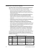
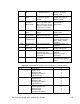
6 Analog Input (AI) Senses current, voltage, or resistance inputs 7 Analog Output (AO) 8 Analog Function Block (AFB) 9 PID Controller (PID) Real Time Clock (RTC) Event Scheduler (ES) Drives current, voltage, or resistance analog outputs Performs functions on two analog values and a digital value such as add, subtract, multiply, divide, greater than, less than, enthalpy, and comparison Performs closed-loop control Maintains date, day of week, and time of day Schedules system events 10/11 10/11 10/
AI-10 AO-10 SCH-10 (with SCH-10 application) SCH-10 (with DL10 application) Type Translator Node Object Analog Input Digital Encoder Analog Function Block Type Translator Node Object Analog Output PID Controller Digital Encoder Analog Function Block Type Translator Node Object Real Time Clock Event Generator State Machine Node Object Data Logger Real Time Clock 6 1 2 2 4 4 1 2 2 1 2 2 1 1 1 1 1 1 1 Each functional block has a number of network variables, through which data is passed to or from the func
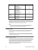
The LonPoint AI-10, AO-10, DI-10, and DO-10 applications have been upgraded to version 3, but many of the devices currently available still have the version 2 applications loaded into them. The version 3 applications have been certified to meet the LONMARK Interoperability Guidelines. The program ID for all four applications has been changed to indicate a LONMARK.
LONMARK Certified: Yes The DI-10 device’s version 2 and version 3 applications have different Device Class values, so the LonMaker tool will issue a warning when an attempt is made to load a version 3 DI-10 application into a device which currently contains a version 2 DI-10 application. This warning may be safely ignored. The SCH-10 device supports two applications, the SCH-10 application and the DL-10 application.
any downstream functional blocks that check heartbeats to go into heartbeat failure as well. Functional blocks which go into heartbeat failure will output their default values (see Defaults, below) You can disable heartbeat receive checking on downstream functional blocks. This may be desirable in situations where it makes sense for the application to continue to use the last known valid data rather than change to the configured default network variable or hardware output.
transferred to the new device. The new device will not necessarily be in the same override state as the old device. Network Variables On the first tab of the LonPoint Plug-in window for each LonPoint functional block (except for the Node Object) there is a network variable shape for each network variable which looks like this: To get information about a network variable, click on the network variable shape.
Changing Network Variable Types You can change the types of some network variables in LonPoint functional blocks. Most changeable types are either floating-point or enumerated network variables, as well as the network variables in the Type Translator functional block. Changing the type of a network variable will reset its format to the default for that type. This affects the display of related fields in the LonPoint Plug-in. See Network Variable Formats for more information.
type file containing the new network variable type from this list. Type List Lists all network variable types in the selected file that are compatible with the selected network variable. Select the new network variable type from this list. Compatible Types Indicates how compatibility is decided. For all functional blocks except the Type Translator, this is by Base Type (e.g., floating-point or enumeration).
This dialog contains the following fields: Network Variable Name The name of the network variable. This field is read-only. You can change the name of a network variable using the LonMaker tool. Previous Format The current format of the selected network variable. This field is read-only. Format Lists the available formats for the selected network variable type.
1-12 LonPoint System Overview
2 The Digital Input Functional Block: Application and Plug-in This chapter describes how to configure a Digital Input functional block using the LonPoint Plug-in.
The Digital Input Functional Block The Digital Input functional block reads the state of a digital signal. This value is then processed, and the resulting digital value is sent to the output network variable. The following figure and table summarize the inputs and outputs of the Digital Input functional block: Output Network Variables Default name Default type Digital SNVT_switch Description The Digital output network variable driven by the sensor.
Digital Input The Digital Input tab, pictured below, provides a graphical interface to the LonPoint Digital Input (DI) functional block. It allows you to determine how data from a physical digital input is interpreted and what value is sent over the network on the DI functional block’s output network variable. The data flow in this tab is left to right.
found. This field may contain up to 30 characters. This value is separate from the device’s location property. Processing Affects the translation of incoming data to the value passed to the output network variable. There are five processing options: Direct, Delayed, Toggled, Pulsed, and One-Shot. The Direct option causes data to be output directly after the debounce and invert functions have executed.
the new values to be used for the delay. The valid range for this value is from zero to 48 days, 23 hours, 59 minutes, 59 seconds, and 999 milliseconds. Off Delay Time Use this field with the Delayed Processing option. This value determines the length of the delay in the change from the on state to the off state. To change the value, click the button to the right of the time value to be changed and enter the new values to be used for the delay.
Status This tab allows you to view and change the status of a Digital Input functional block. This tab appears as follows: This tab contains the following fields and buttons: 2-6 Device Version The version number of the application in this device. The minor version number (after the decimal point) is always read from the device itself. If the network is unattached or Offnet, the minor version number will read XX (e.g. 2.XX). Error Log The most recently logged error on the device.
Blocks, and Routers in the LonMaker for Windows User’s Guide. Object Version The version number of this functional block. The minor version number (after the decimal point) is always read from the device itself. If the network is unattached or Offnet, the minor version number will read XX (e.g. 2.XX). Disabled Indicates Yes if this functional block is disabled, No if it is enabled, and ? if the plug-in is not in communication with the device.
2-8 Digital Input Functional Block
3 The Digital Input/Counter Functional Block: Application and Plug-in This chapter describes how to configure a Digital Input/Counter functional block using the LonPoint Plug-in.
The Digital Input/Counter Functional Block The Digital Input/Counter functional block reads the state of a digital signal. This value is then processed, and the resulting value is sent to the digital output network variable. The Digital Input/Counter is a superset of the Digital Input; it contains all the functionality of the Digital Input plus additional capabilities.
following tabs, Digital Input/Counter, Processing Parameters, Translation, Output Parameters, and Status. Digital Input/Counter The Digital Input/Counter tab, pictured below, provides a graphical interface to the LonPoint Digital Input/Counter (DC) functional block. It allows the user to determine how data from a hardware digital input is interpreted and what value is sent over the network on the Digital Input/Counter functional block’s output network variables. The data flow in this tab is left to right.
remain constant for the value to be passed on to the rest of the functional block. Set this value to 0 to turn off the debounce function. Inversion Specifies whether or not the data from the digital input is inverted before further processing is done. Determines whether a high voltage level is interpreted as an On state (not inverted) or an Off state (inverted). Processing Affects the translation of incoming data to the value passed to one of the output network variables.
block is configured with the Toggled option, the digital network variable output value will change every time the button is pushed. Pulsed Generates a pulse on the digital output network variable every time the input data changes from Off to On. The pulse is generated after a delay specified on the On Delay Time field. The duration of the pulse is specified on the Pulse Time field.
DRY_CONTACT: minimum period = min(500ms, 2 * debounce interval) maximum frequency = 1/minimum period 5V, 12V, 24V, or 32V : maximum frequency = 20kHz Repeating Count Counts the off to on transitions from zero up to a configurable value called the terminal count. When the Digital Input/Counter reaches the terminal count the count is reset to zero.
output goes On and the count as reported by the Analog network variable is set to 0. Cans continue: 1, 2…, then, some downstream device controlling the boxing process sees the Digital network variable to be on, boxes the cans, and sends CLEAR to the Control network variable. The digital output goes Off. Cans continue three, zero and the process repeats.
Frequency Measures the frequency of the input signal in the range of 1Hz to 20kHz. Minimum resolution of the frequency measurement is <0.5% over the full measurement range. The Analog network variable reports the instantaneous measured frequency or a translated representation of it. The Digital network variable is not used with this processing option. On startup the Analog output network variable is not immediately available as the input is auto-ranged. This process takes up to four seconds.
HOLD Holds the current value of the Analog network variable. Events are accumulated but the network variable is not updated. The HOLD state does not apply to the Repeating Count processing option. The Analog network variable will continue to update if Repeating Count is selected. PAUSE Disables event counting. The internal count value and Analog network variable are not updated. PRESET Presets the counter to the value specified in the preset value configuration property.
Frequency Filter Length This parameter is only used if the processing option is set to Frequency. This value may be set from 1 to 255 and determines the number of readings that are sampled and averaged before a value is passed to the Analog network variable. Default Control Value This parameter is only used if the processing option is set to Count, Repeating Count, or On Time.
Input/Counter software automatically linearly interpolates to determine translation values that lie between defined input/output pairs. The table must contain at least two input/output pairs and may contain as many as twenty. The only constraint on the Measured Value column is that the entries increase in value. To mark the end of the table, enter a measured value less than the preceding one. Click the Save button to save translation table data into a tab-delimited text file.
the Analog network variable. The offset may be positive or negative. The units match the units being sent on the Analog network variable. The offset is applied after the translation. Minimum Value This parameter is only used if the Frequency processing option is being used. This value determines the minimum value that will be sent by the Analog network variable. If this limit is exceeded the output will be clipped at this limit.
4 The Digital Output Functional Block: Application and Plug-in This chapter describes how to configure a Digital Output functional block using the LonPoint Plug-in.
The Digital Output Functional Block The Digital Output functional block controls the state of a digital actuator based on the value of an input network variable. The following figure and tables summarize the inputs and outputs of the Digital Output functional block: Input Network Variables Default name Default type Description Digital SNVT_switch The Digital input network variable that drives the actuator. Mode SNVT_hvac_mode (changeable) The Mode input network variable.
Digital Output This tab appears as follows: This tab displays the flow of information through the Digital Output functional block. It contains the following fields: Location The location string for this digital output. This property can be used to document the associated actuator’s location within the plant so it can be easily found. This field may contain up to 30 characters. This value is separate from the LonPoint device’s location property.
Debounce Determines how long the Digital input network variable and the Mode input network variable must remain stable after a transition in order for the transition to be recognized as valid. This prevents the state from fluttering. This configuration property may be set between 0 and 999 ms. A value of 0 turns the debounce function off. Processing Determines how the debounced input data is translated into the value used to drive the actuator.
length of the delay in the change from the Off state to the On state. To change the value, click the button to the right of the time value to be changed and enter the new values to be used for the delay. The valid range for this value is from zero to 48 days, 23 hours, 59 minutes, and 999 milliseconds. Off Delay Time Use this field with the Delayed Processing option. This value determines the length of the delay in the change from the On state to the Off state.
Input Defaults This tab appears as follows: This tab allows you to set the default inputs for the Digital Value, Mode, and Enable input network variables. The specified input values will be used if the associated network variable is not connected or has not received an update since the device’s last reset.
Presets This tab appears as follows: This tab allows you to set up the preset table which determines how the digital output behaves for each mode value. For each value that the Mode network variable can receive, you can configure whether the output value will be taken from the Digital network variable or will be set to a preset value for the selected mode. Select Use Network Variable to use the network variable value. Select Use Preset Value to use the specified preset value.
Output Parameters This tab appears as follows: This tab allows you to set options determining what information is sent to the output. This tab contains the following fields: 4-8 Default Value Determines the value that will be sent to the hardware if the block is disabled or has detected a heartbeat failure. Override Value Indicates the output value that will be used if the functional block is put into override. This value will be inverted if the Output Invert option is selected.
Heartbeats This tab appears as follows: This tab allows you to set properties that determine the input and output heartbeat rates and feedback sampling. This tab contains the following fields: Input Heartbeat This property determines the interval (in seconds) the network variables that have the Use Heartbeat option selected will wait for a heartbeat before detecting a heartbeat failure. See Heartbeats, in Chapter 1, for more information.
output network variable. This signal can come from a network variable or from the Hand-Off-Auto switch. The signal being sent to the hardware digital output is sampled at this rate, and the network variable is updated whenever the value changes or when determined by the heartbeat. Status This tab allows you to view and change the status of the Digital Output functional block. See Status in Chapter 2 for more information.
5 The Digital Encoder Functional Block: Application and Plug-in This chapter describes how to configure a Digital Encoder functional block using the LonPoint Plug-in.
The Digital Encoder Functional Block The Digital Encoder functional block performs logic functions on four digital input network variables to create a digital output network variable and a mode output network variable. The following figure and tables summarize the inputs and outputs of the Digital Encoder functional block: Input Network Variables Default name Default type D1/D2/D3/D4 SNVT_switch Description Four digital input network variables which are processed by the Digital Encoder.
Digital Encoder This tab appears as follows: This tab displays the flow of data through the Digital Encoder functional block. This tab contains the following fields: Delay Specifies the amount of time the digital inputs must stay constant before they are processed. The value must be between zero and 48 days, 23 hours, 59 minutes, 59 seconds, and 999 milliseconds. To change the value, click the button to the right of the time value to be changed and enter the new values to be used for the delay.
Lookup Tables This tab appears as follows: This tab contains the lookup table that determines the output of the Digital_Out and Mode_Out network variables based on the values of the 4 digital inputs. Each row of the table corresponds to one of the 16 possible combinations of input values from the four digital inputs. For each combination of inputs, you can set an output value for the Digital_Out network variable in the Digital Output column and the Mode_Out network variable in the Mode Output column.
For example, to create a digital encoder block that returns an On value on the Digital Output when the D3 AND D4 inputs are on and on Off value otherwise, enter a value of 0 in the Digital Output column in the first 12 rows (in which either or both of the D3 and D4 inputs are 0) and a value of 200 in the Digital Output column in the remaining rows (in which both D3 and D4 have a value of 1), as follows: The LonPoint Application and Plug-in Guide 5-5
To create a table that sends an HVAC_EMERG_HEAT mode on the Mode_Out network variable if any of the four inputs are On and HVAC_AUTO if they are all Off, you would set the Mode Output column to HVAC_EMERG_HEAT in all the rows but the first (in which at least one of the four inputs has a value of 1) and to HVAC_AUTO in the first row (where all four inputs are 0), as follows: 5-6 Digital Encoder Functional Block
Heartbeats This tab appears as follows: This tab allows you to set heartbeat and throttle options for the input and output network variables on the Digital Encoder functional block. This tab contains the following fields: Input Heartbeat Determines the interval (in seconds) the network variables that have the Use Heartbeat option selected will wait for a heartbeat before registering a heartbeat failure.
this field to zero to disable heartbeats for both output network variables. Throttle Determines the throttle, in milliseconds, for both output network variables. This is the minimum amount of time between two network variable updates. Set this field to zero to disable throttling for both output network variables. Status This tab allows you to view and change the status of a Digital Encoder functional block. See Status in Chapter 2 for more information.
6 The Analog Input Functional Block: Application and Plug-in This chapter describes how to configure an Analog Input functional block using the LonPoint Plug-in.
The Analog Input Functional Block The Analog Input functional block measures the voltage, current, or resistance of a hardware transducer. This value is then translated into an appropriate value to send on the Analog output network variable. For example, a temperature transducer might return a value of 10,000 to 15,000 ohms. The Analog Input functional block translates this raw value into the appropriate temperature value using a translation table.
Analog Input This tab appears as follows: This tab shows the flow of information through the Analog Input functional block. It contains the following fields: Measurement Type Determines whether the input reads voltage (Volts), current (Amps), or resistance (Ohms). The value in this field must match the hardware settings on the associated LonPoint module. See the LonPoint Hardware and Installation Guide for information on changing the hardware settings.
Measurement Type, Measurement Current, and Input Gain values. Filter Sets the input noise filtering on the device to reject either 50 Hz or 60 Hz noise. Translation Enabled Determines whether the translation table, set up in the Translation tab, will be used. If this option is disabled, the untranslated, or raw, values will be used as read from the transducer. Device Offset The value set in this field is added to the sensed reading to account for device-to-device transducer variations.
Translation This tab appears as follows: This tab allows you to set up a translation table that translates the raw measured data into the values to be sent over the Analog output network variable. The translation table provides a means for mapping any input set of values into a different set of output values via pairs of input/output values. The Analog Input software automatically linearly interpolates to determine translation values that lie between defined input/output pairs.
All fields on this tab will be disabled if the Translation Enabled option is not set on the Analog Input tab. Output Parameters This tab appears as follows: This tab determines how often data is sent on the Analog network variable and the minimum, maximum, and override values. This tab contains the following fields: 6-6 Minimum Value The minimum value that will be sent by the output network variable. If this limit is exceeded the output will be clipped at this limit.
Heartbeat Determines how often the functional block sends a heartbeat over the network. The behavior of the system in case of a failed heartbeat is determined by the functional blocks which fail to receive the heartbeat. Setting this property to 0 disables the heartbeat for this functional block. Disabling the heartbeat causes the output network variable to only be transmitted in response to a changed hardware input value.
current setting is determined by two factors: absolute range and self-heating limitations. The absolute range refers to the upper input voltage limit of the A/D converter after voltage input scaling: 2.500VDC (scaling allows measurement of voltages higher than this limit). Any voltage higher than this limit will not be measurable. The maximum resistance that can be measured at 25µA is 2.5V/25e-6A = 100kΩ, and at 400µA is 2.5V/400e-6A = 6.25kΩ. Resistances higher than 100kΩ at 25µA, or 6.
Volts Measurement Type (VOLT Jumper Setting) Voltage measurement involves applying voltage across the Base Plate input terminals (10-11 or 12-13), making sure to note the correct polarity, setting the gain accordingly, and then reading the voltage. The input resistance of the AI10 in voltage mode is 7,246Ω ± 0.3%, and the attached sensor must be able to drive that load in order to obtain consistent results.
6-10 Analog Input Functional Block
7 The Analog Output Functional Block: Application and Plug-in This chapter describes how to configure an Analog Output functional block using the LonPoint Plug-in.
The Analog Output Functional Block The Analog Output functional block translates an input network variable value to a value that is used to drive a hardware output. The functional block may be configured to translate the value into voltage or current, depending on the requirements of the hardware output being driven.
Analog Output This tab appears as follows: This tab sets configuration properties that determine how the values received by the input network variables are processed by the functional block and what values are sent to the physical actuator. This tab allows you to set the following fields: Location The location string for this analog output. This property can be used to document the associated actuator’s location within the plant so it can be easily found. This field may contain up to 30 characters.
selected, the input range is 0 to 100%. Input ranging is useful for split-range applications where a single value drives multiple actuators, but each actuator is active over a different input range. The analog output functional block can be configured to be reversing (i.e. go from 0% to 100% as the input goes from 100% to 0%) by switching either the Input Range or the Output Range values. Output Range Defines the minimum and maximum range of the output.
Mode Default This value will be used if the Mode network variable is not connected or has not received an update since the last device reset. Enable Default This value will be used if the Enable network variable is not connected or has not received an update since the last device reset. Output Default This value will be sent to the physical actuator if the functional block is disabled or has detected a heartbeat failure.
Heartbeats This tab appears as follows: This tab allows you to configure the input heartbeat rates. This tab contains the following fields: Input Heartbeat Determines the interval (in seconds) the network variables that have the Use Heartbeat option selected will wait for a heartbeat before registering a heartbeat failure. Use Heartbeat Specifies whether or not heartbeat checking will be used for the selected input network variables.
8 The AFB Functional Block: Application and Plug-in This chapter describes how to configure an Analog Function Block (AFB) functional block using the LonPoint Plug-in.
The Analog Function Block (AFB) Functional Block The AFB functional block performs mathematical, logical, or enthalpy functions using up to 2 analog inputs and a digital input (not all inputs are used for all functions). The following figure and tables summarize the inputs and outputs of the AFB functional block: Input Network Variables Default name Default type Description A1/A2 SNVT_temp_f (changeable) Two Analog input network variables that are processed by the AFB functional block.
Analog Function Block This tab appears as follows: This tab displays the flow of information through the AFB functional block. For each of the analog inputs, use the Inputs tab to determine whether the A1 or A2 network variable value or a constant value will be used. Use the Function tab to specify the function to be performed on the two values.
Inputs This tab appears as follows: This tab determines what values are used for the analog operands. For each of the two operands, you can use the associated network variable by selecting Use Network Variable, or use a constant by selecting Use Constant and setting the corresponding field to the desired constant value. The constant type depends on the input network variable type specified on the Analog Function Block tab.
Analog Input network variable is formatted as SNVT_temp_f#US_diff, this option is disabled and Differential is automatically selected. This option can only be modified by the user if you are using a Logic function (see the Function tab).
Function This tab appears as follows: Function Type Determines whether the analog function block performs a Logic, Math, or Enthalpy function. The Logic Function options determine what operation will be used if the function type is set to Logic. The following options are available: 8-6 High Select The higher of the two analog operands will be sent to the analog output. Low Select The lower of the two analog operands will be sent to the analog output.
Less Than The Digital_Out network variable will be set to On if the value from Operand 1 is less than the value from Operand 2. Otherwise, an Off value will be sent. Changes to the output value are affected by the Hysteresis value (see below). Greater Than or Equal The Digital_Out network variable will be set to On if the value from Operand 1 is greater than or equal to the value from Operand 2. Otherwise, an Off value will be sent.
Outputs This tab appears as follows: This tab determines what value is sent to the A_Out and Digital_Out network variables based on the output from the Math, Logic, or Enthalpy function performed by the Analog Function Block. 8-8 Delay Specifies a time that the result of the calculation made by the AFB must remain constant to be sent on the appropriate output network variable. The value can be up to 48 days, 23 hours, 59 minutes, 59 seconds, and 999 milliseconds.
The type of the values in the Output column depend on the Analog Output network variable type you selected on the Analog Function Block tab. The type of the values in the Input column cannot always be determined. For Add and Subtract functions the units are normally displayed. All other cases show units as ? (Native) and the values shown are in (or derived from) the native units of the input network variables (normally SI units). Caution should be used when scaling Fahrenheit temperatures.
Heartbeats This tab appears as follows: This tab determines the heartbeat and throttle values for the input and output network variables. This tab contains the following fields: 8-10 Input Heartbeat Determines the interval (in seconds) the network variables that have the Use Heartbeat option selected will wait for a heartbeat before detecting a heartbeat failure. Use Heartbeat Determines whether the associated input network variable uses heartbeat checking.
network variable updates. When the throttle time expires, only the most recent change to the output value is transmitted. Set this value to zero to disable throttling. Status This tab allows you to view and change the status of an AFB functional block. See Status in Chapter 2 for more information.
8-12 Analog Function Block Functional Block
9 The PID Controller Functional Block: Application and Plug-in This chapter describes how to configure a PID controller functional block using the LonPoint Plug-in.
The PID Controller Functional Block The PID Controller functional block controls an output network variable value based on an input process variable and setpoint. The process variable is obtained from a sensor that measures an environmental condition, such as temperature or air pressure. The setpoint indicates the desired value of the process variable. The PID controller reads these values and based on the PID algorithm, outputs a value known as the controlled variable.
Enable SNVT_switch The enable network variable. If this network variable is set to On, the PID Controller functional block will function normally. If this network variable is set to Off, the output network variables on this functional block will return to their defaults. Output Network Variables Default name Default type Description CV SNVT_lec_cont_f SP_Out SNVT_temp_f (changeable) The setpoint output network variable. This network variable outputs the setpoint being used by this PID Controller.
PID This tab appears as follows: This tab displays the flow of information through the PID functional block. The input values are taken from network variables on the left. The information is passed through the preset tables to determine what values are sent to the PID controller. The PID controller calculates the controlled variable and outputs it to the controlled variable network variable on the right, along with the actual setpoint and auto/manual settings used.
Input Defaults This tab appears as follows: This tab sets the default input values for the input network variables. As described in Default Values in Chapter 1, these values will be used if the corresponding input network variables are not connected, or have not received an update since the last device reset. The types of the Process Variable, Setpoint, and Mode values depend on the types selected or the corresponding network variables on the PID tab.
Presets This tab appears as follows: This tab configures the preset tables. Each preset table can contain up to 16 entries. The View Mode field determines which one of the entries is currently being configured. When the PID is running, the preset tables are indexed by the PID’s Mode network variable to determine which value will be used. Each entry in a preset table specifies the source of the value controlled by the preset.
preset value. The Manual Value will only be used when the Auto/Manual value is set to Manual, and the Setpoint will only be used if it is set to Auto. PID Coefficients This tab appears as follows: This tab sets values that effect the algorithm used by the PID controller. This tab allows you to set that following configuration properties: P The proportional term of the PID controller. Its units are percent output per process variable unit as specified on the PID tab.
Bias Sets the controlled variable output for a P-only controller when there is zero error. This is only used if the integral (I) term is 0. Deadband When the difference between the setpoint and the process variable is less than this value, no controlled variable adjustment is made. The process variable is considered close enough. Deadband may be used to reduce actuator wear. Cascade Causes the controlled variable to react more strongly to changes in the setpoint for the PI and PID configurations.
Output Parameters This tab appears as follows: This tab sets properties that effect the value output from the PID controller, and also determines the override values. Max Slew Rate Limits how fast the controlled variable output can change. This limit is in effect only during soft start. Soft start begins when the functional block is reset and it ends when the process variable value reaches the setpoint. Units are percent output change per scan interval (set in the Heartbeats tab).
Default Values The default value for the controlled variable output. This value will be set in case of a heartbeat failure or if the PID is disabled using the Enable input. Controlled Variable Override Sets the value of the controlled variable output when this PID functional block is put into override mode. Actual Auto/Manual Override The Auto_Man_Out network variable indicates whether the PID is in Auto (On Auto_Man_Out output) or Manual (Off Auto_Man_Out output) operation.
Heartbeats This tab appears as follows: This tab determines input and output heartbeats, as well as the execution rate of the PID controller. Input Heartbeat Determines the interval (in seconds) the network variables that have the Use Heartbeat option selected will wait for a heartbeat before registering a heartbeat failure. Use Heartbeat Determine whether the corresponding network variable checks its heartbeat.
failure conditions are determined by the functional blocks that contain the corresponding input network variables. Status This tab allows you to view and change the status of a PID controller functional block. See Status in Chapter 2 for more information. LonPoint PID Controller Tuning This section describes a simple method that can be used to set initial values for the PID coefficients.
possible step is not necessarily better than a small step; you have to wait longer for the large step to reach its new process value. Too small of a step will make it too hard to see when the process has settled. This example uses a 20% step size. To perform the experiment and calculate the PID coefficients, follow these steps: 1. Open your design with the LonMaker tool, making sure to put your network OnNet. 2. Right-click the PID controller function block and select Browse from the context menu. 3.
variable delta, delta PV, is the difference between the final and initial process variable readings; the control variable step causes a process variable change of delta PV. In the next part of the experiment, the dynamic properties of the process are found. There are two time intervals that need to be measured. They are named T1 and T2. Both intervals start when the control variable step change is made. T2 is the time required to attain 28.8% of delta PV. T1 is the time required to reach 63.2% of delta PV.
4. Enter the T1 and T2 times into the calculator and click the Calculate button. The PID coefficients are shown in the grid: The various options are shown in the left-hand column. Sets of coefficients for a Ponly controller, a PI controller and a PID controller are shown. Blanks represent zero values for the associated parameters. For example, if you want a PI controller, set P = 8.45, I = 3.80, and D = 0.
Go back to the LonMaker tool to configure the PID. Right-click the PID Controller functional block and select Configure from the shortcut menu. Enter the PID coefficients using the PID coefficients tab as shown below. A cascade arrangement is where an outer PID controller’s control variable is used to drive the setpoint of an inner PID controller. The inner controller must react strongly to changes in its setpoint.
The Reverse Acting process option is not used in this example. This is because the process is forward acting; an increase in the control variable causes an increase in the process variable. For a reversing process, the Reverse Acting process option must be selected, so the controller moves the control variable in the proper direction.
9-18 PID Controller Functional Block
10 The Scheduler Functional Blocks: Application and the ™ LonPoint Schedule Maker This chapter describes how to configure a LonPoint SCH-10 Scheduler Module containing Real-Time Clock, Event Scheduler, and State Machine functional blocks, using the LonPoint Schedule Maker utility. Chapter 11 describes the LonPoint Schedule Keeper utility that can be used by ad operator to modify an existing schedule.
Using the SCH-10 Scheduler Module The SCH-10 Scheduler Module is a general-purpose controller that can be used as a source of system time, a time-based event scheduler, and a general-purpose state machine. The SCH-10 module includes a downloadable flash memory that is preprogrammed with the SCH-10 scheduler application. The SCH-10 module also includes a real-time clock with battery backup.
schedule consists of a time (in hours and minutes) and an event. This event has a name and an On or Off value. For example, an event called evtEnableAlarm may be set to On at 7:00 PM and set to Off at 7:00 AM. When the time input to the Event Scheduler functional block equals the specified time for an event, the Event_Out output is set equal to the event.
daytime scheduled event on, the smoke detector digital input off, and the room temperature analog input greater than 20ºC. The following figure illustrates the typical configuration of the SCH-10 functional blocks in a LonMaker design.
Types of Schedules The State Machine functional block can be used to implement two types of schedules – a digital output schedule and a state output schedule. When using a digital output schedule, the digital outputs from the State Machine functional block are controlled directly by the Event_Out output from the Event Scheduler functional block. This type of schedule is useful for schedules that are strictly based on time of day, since the complexity of defining a state machine is eliminated.
The first step is to create a text description of the sequence of operations for the supervisory application design. This description should be stored in your LonMaker drawing using a Visio text box. Steps 2 and 3 are completed within your LonMaker drawing using shapes from the Schedule stencil. You will manually transfer the schedule design that you create in these steps to the LonPoint Schedule Maker utility in steps 4 through 6.
6. Repeat steps 2 through 5 for each unique daily schedule. Assign a different schedule name to each. Following is an example daily schedule. Daily Schedule Schedule Name: schOccupied Event Name ON or OFF Time evtOccupied Off 12:00 AM evtWarmup On 6:00 AM evtWarmup Off 8:00 AM evtOccupied On 8:00 AM evtOccupied Off 7:00 PM 1. Use an additional Daily Schedule shape for each 24 hour schedule. 2. Use a second Daily Schedule shape for additional events for the same schedule. 3.
Following is an example default schedule. Default Daily Schedule Day Daily Schedule Name Sunday schUnoccupied Monday schOccupied Tuesday schOccupied Wednesday schOccupied Thursday schOccupied Friday schOccupied Saturday schUnoccupied Optional Description Assigning Override Daily Schedules An override daily schedule may be assigned to any range of dates.
Creating a State Machine Design A state machine design defines one or more states for the State Machine functional block. In the following examples, state names start with an st prefix, so example state names are stOn and stOff. A simple system may have only these two states. An example of a more complex design is an HVAC system with additional states such as stOccupied, stUnoccupied, stWarmup, and stEmergency. Each state has one or more transitions to other states.
other functional blocks in your system. To simplify using these inputs and outputs, you will assign names to each input or output that you plan to use. These names are only used in your schedule design, and are not downloaded to the SCH-10 module. In the following examples, input names start with an i prefix and output names start with an o prefix (except when using a digital output schedule as described in the next paragraph), so example names are iSystemEnable and oOccupied.
Event Scheduler functional block, i.e., if you are using a digital output schedule. Following are example digital and analog input name shapes with example names and descriptions.
Digital Outputs Digital Output Names Optional Description and Type D_Out_1 evtOccupied For setpoint and lighting control D_Out_2 evtWarmup Morning warmup control D_Out_3 D_Out_4 D_Out_5 D_Out_6 D_Out_7 D_Out_8 D_Out_9 D_Out_10 D_Out_11 D_Out_12 D_Out_13 D_Out_14 D_Out_15 D_Out_16 10-12 Scheduler Interface
Following is an example of the Digital Outputs shape for a state output schedule, with example names and descriptions.
when the system is enabled and the outdoor air temperature is cooler than the indoor air temperature. This transition may put the system into heating mode. For each transition, you will define an exit condition. An exit condition is a formula that specifies logical and arithmetic operations on the State Machine inputs. When the State Machine functional block executes, it evaluates each of the exit conditions for the transitions defined out of the current state.
Following is an example bubble diagram. This diagram defines five states and the transitions between them.
the Mode_Out network variable, and the D_Out_1 through D_Out_16 digital output network variables. To define state transitions, follow these steps for each state that you defined in the previous section: 1. Drag a State Definitions shape from the LonPoint Schedule stencil to your LonMaker drawing. 2. Double-click the State Definitions shape. A drawing of the shape opens in a new window. 3. Click on the box to the right of the State Name label. 4. Fill in the name of the state from the bubble diagram.
6 HVAC_OFF Controller not controlling outputs 7 HVAC_TEST Equipment being tested 8 HVAC_EMERG_HEAT Emergency heat mode (heat pump) 9 HFAC_FAN_ONLY Air not conditioned, fan turned on 255 HVAC_NUL Value not available 4. Click the corresponding entry in the Digital Output Values column and type the names of all the digital output network variables that should be on after this transition. The digital outputs are all SNVT_switch values, and you will specify each as either On or Off.
Defining Exit Conditions An exit condition is a specification for the conditions under which a transition should be followed in a state machine. An exit condition is defined as a combination of events from the Event Scheduler functional block and the values of the State Machine functional block’s input network variables. An exit condition is defined as a logical expression consisting of multiple terms separated by AND and OR. Each term is an expression with a True or False result.
evtWarmup OFF To define exit conditions, follow these steps: 1. Drag a Condition Definitions shape from the LonPoint Scheduler stencil to your LonMaker drawing. 2. Double-click the Condition Definitions shape. A drawing of the shape opens in a new window. 3. For each exit condition definition, click an entry in the Exit Condition column and type an Exit Condition name. Then click an entry in the Definition column and type an Exit Condition expression. Close the Exit Condition shape drawing window.
Starting and Exiting the LonPoint Schedule Maker Utility Once a schedule design is complete, the design must be manually transferred to the LonPoint Schedule Maker utility. LonPoint Schedule Maker is a stand-alone Windows application that is used to create, edit, and save schedule design files. LonPoint Schedule Maker is also used to simulate designs, and to download completed designs to SCH-10 modules.
Set the starting and ending dates and times to the same value to disable Daylight Savings Time. The first time you use an SCH-10 module, you will also need to set the time using the LonMaker Browser. This procedure is described in Setting the SCH10 Time later in this chapter. Configuring the Event Scheduler Functional Block The Event Scheduler functional block generates time-based events that are used by the State Machine functional block.
The following section describes how to transfer the daily schedules, default daily schedules, and override daily schedules to the Edit Schedules tab. Configuring Daily Schedules A daily schedule defines times for On and Off events over a 24-hour period starting from midnight and going to 11:59PM. Daily schedules are described in Defining Daily Schedules earlier in this chapter. To transfer a daily schedule design to Schedule Maker, follow these steps: 1. Select the Edit Schedules tab. 2.
The following figure shows a daily schedule design for the schOccupied schedule design described in Defining Daily Schedules. Configuring Default Daily Schedules Default daily schedules specify a daily schedule to be used by default for each day of the week. These defaults may be overridden for any range of dates as described in the next section. Default daily schedules are described in Assigning Default Daily Schedules earlier in this chapter.
The following figure shows a default daily schedule for the schedule design described in Assigning Default Daily Schedules. Configuring Override Daily Schedules Override daily schedules specify a daily schedule to be used for a specified range of dates. Override daily schedules are described in Assigning Override Daily Schedules earlier in this chapter. To transfer an override daily schedule design to the LonPoint Schedule Maker utility, select the Edit Schedules tab.
The following figure shows the override schedules for the schedule design described in Assigning Override Daily Schedules. Configuring the State Machine Functional Block The State Machine functional block controls up to 16 digital outputs and a mode output based on transitions between states. Each transition has an exit condition that defines when the transition should be followed.
When this option is selected, the digital output names must match the event names as described in Defining Inputs and Outputs earlier in this chapter. The outputs must be named as described in Assigning Input/Output Names in the next section, and at least one state with one exit condition must be defined, even if you are not using the Mode_Out output from the State Machine functional block. Configuring a State Machine Three tabs are used to configure a state machine.
This tab contains four tables that allow you to assign names to each of the 8 analog inputs, 8 digital inputs, and 16 digital outputs, and to define up to 10 system parameters. Only network variable names that will be used in other tabs need be assigned; the other names may be blank. These network variable names are used only within the LonPoint Schedule Maker utility to provide meaningful names for the network variables when used in exit condition definitions.
The following figure shows the input/output names for the schedule design described in Defining Inputs and Outputs earlier in this chapter as well as several named constants.
Defining the State Machine The Edit State Machine tab, shown in the following figure, allows you to define the state names and transitions for the State Machine functional block. The Current State field is used to enter new state names, and to select a state to define. The state table, contained in the Define Transitions from the Current State frame, allows you to define the state transitions from the state selected in the Enter or Select State field. The state table contains 3 columns.
2. Click the Current State field. For each bubble in your bubble diagram, enter the name of the state and press the Enter key. The new state is added to the States list. 3. Select the initial state identified in your bubble diagram in the Select Initial State field. Warning: If you forget to select an initial state, your schedule will not simulate or operate correctly. 4. Click the Exit Conditions field.
Defining Exit Conditions The Edit Conditions tab, shown in the following figure, allows you to define the exit conditions that you created in the Edit State Machine tab. To define exit conditions, select the Edit Conditions tab. For each exit condition, follow these steps: 1. Select the exit condition name in the Select Exit Condition list. 2. Enter the condition definition in the AND/OR table at the bottom of the tab. Your definition should consist of terms separated by AND and OR statements.
the expression. When you have completed the expression, press Enter to transfer the expression to the selected cell in the AND/OR table. • For a mode input term, select the IS or IS NOT modifier, and click on the mode value to copy the term to the current cell in the AND/OR table. • For a digital input term, select the ON or OFF value and click on the digital input name in the Digital Inputs list value to copy the term to the current cell in the AND/OR table.
Setting Scheduler Options The Settings tab, shown in the following figure, allows you to determine data flow configuration properties for the Event Scheduler and State Machine functional blocks. This tab contains the following properties: Input Heartbeat Determines the interval (in seconds) the network variables that have the Uses Heartbeat option selected will wait for a heartbeat before registering a heartbeat failure. See Heartbeats in Chapter 1 for more information.
default value of 100ms. Uses Heartbeat Specifies whether or not heartbeat checking will be used for the selected input network variables. Each of the input network variables named in the Name I/O tab plus the Mode and Event input network variables are included. Daylight Savings Time Defines when Daylight Savings Time starts and stops. See Configuring the Real Time Clock Functional Block earlier in this chapter.
To start a new design, or to save or load a design file, select the Load/Save tab. The following buttons are used to create, load, and save design files: To create a new design, click the New Design File button. This clears all entries on the Schedule Maker tabs so that you can create a new design. To save a design, follow these steps: 1. Click the Save Design File button. 2. Locate a drive and folder for the schedule design file. 3. Enter a file name. You do not have to type the .DSG extension. 4.
module will function as expected. You will use the Simulate tab, shown in the following figure, to interact with the simulator. The Simulate tab shows a graphical representation of the data flow within the SCH-10 application. The following sections describe how to use this tab to simulate a design. This tab displays the following information: Inputs Controls the simulated input values for the mode, digital, and analog input network variables of the State Machine functional block.
The Current Schedule field indicates what daily schedule is currently being used. You can manually set the schedule by clicking on the Manual Schedule button as described in Overriding the Event Schedule later in this chapter. Condition Status Displays the status of the events defined in the Edit Schedules tab.
3. Click the Eval Next Cond button. The next condition specified for the current state is evaluated, and the results are displayed in the simulator tab. If there are more conditions to be evaluated, the Change Mode button is disabled and the Eval Next Cond button is still displayed. If there are no more conditions to be evaluated, the Eval Next Cond button is hidden and the Change Mode button is reenabled.
Manually Entering Time and Date You can manually change either the time or date in the simulator in order to verify operations at future times/dates. Whenever either field is manually changed, the simulator will automatically perform a reset by backing up twentyfour hours for the new time/date and fast forwarding to the new time/date while simulating all events in the last twenty-four hours in order to get the state machine in a state that is current relative to the new date and time.
Adding the Scheduler Functional Blocks Once you have successfully simulated a design, you must install the SCH-10 device and functional blocks using the LonMaker tool. You can install the device and functional blocks individually and connect them as shown in the following figure. At least one of these shapes must be in your top-level subsystem, or you can put these shapes in any subsystem and add a Node Object functional block for the SCH-10 device to your top-level subsystem.
Downloading a Supervisory Application Design The supervisory application design is downloaded to the LNS Server, and optionally an SCH-10 module, using the following Load/Save tab. To download the design into an LNS Server, and optionally a SCH-10 module, follow these steps: 1. Select Local Server if you are running on the same PC with the LNS Server; uncheck Local Server if you are running on a remote PC. 2.
Maker utility can only configure SCH-10 modules that have device or functional block shapes in this top-level subsystem. 7. Select the SCH-10 device to be configured in the SCH-10 Devices list. 8. Click the Download Design button to configure the selected device. Any previous schedule design for the device will be overwritten. The download may take one to five minutes depending on schedule size and network load. If you are OnNet, you can speed up downloading by turning off monitoring in the LonMaker tool.
3. Right-click the State Machine functional block and select Browse from the shortcut menu to open the LonMaker Browser. 4. Right-click the Mode or Mode_Out network variables and select Change Type from the shortcut menu. The Change Network Variable Type dialog appears. 5. Select a new network variable type from the Type List. The Standard Network Variable Type option allows you to select the type from the SNVTs detailed in the SNVT Master List help file.
event. If connected, the State Machine functional block will respond to the updated input. Note: When Debug Enable is On and DebugNext is updated and On, the Event Scheduler emits the next event. While the EventScheduler is looking up the next event, it also is responding to the network variable polls at a slowed rate. If you select the Stop Automatic Display option of the LonMaker Browser Message dialog box, you can stop message flow.
11 The Schedule Keeper Utility This chapter describes how to use the LonPoint Schedule Keeper utility to modify a schedule created using the Schedule Maker utility.
The Schedule Keeper Utility The LonPoint Schedule Keeper utility is used by system operators to perform limited on-site modification to a supervisory application after it has been downloaded into an SCH-10 device. This utility allows the operator to change the times when scheduled events will be triggered and modify which days on the special schedules will be used. It does not allow the operator to create new schedules or new events.
3. Right click the shortcut and select Properties. 4. Click the Shortcut tab and enter the desired command line in the Target field. For example, to create a shortcut that starts Schedule Keeper for the specified schedule in super user mode, enter the following command line: C:\LonWorks\Apps\Echelon\LonPoint\schkeepr.exe /S /L "C:\LonWorks\SchApp\Launch\Fullsm1.NewNet.NewNet.Subsystem 1.SCH- 1.
The example above shows a typical weekday schedule for a building. The Weekday schedule has four events. At midnight, the EnableUnoccupiedOps event is turned on. This event could involve shutting down heating and light and turning on an alarm system. At 6:00 AM, this event is turned off. At 6:01, the EnableMorningWarmup event begins. This event could involve turning on heaters and any other machinery that requires a warmup period.
Modifying the Daily Default Schedule Click the Daily Defaults button to open the following window: This window allows you to determine which schedule will be used on each day of the week by default (see Modifying Schedule Overrides, in the next section, for information on overriding the default schedule). Click an entry in the Schedule column to select a new daily schedule from a list of all daily schedules available on this SCH-10 device.
Modifying Schedule Overrides Click the Overrides button to open the following window: This window allows you to view, add, remove, and modify dates during which the daily default schedules (see Modifying the Daily Default Schedule, earlier in this chapter) will be overridden. In the example above, the Holiday schedule is configured to be used on December 22, June 1 to June 7, and August 20 to August 24th.
Click Remove Entry to delete an override schedule. A dialog opens asking you which entry you would like removed. Enter the number displayed at the left end of the row containing the schedule override period to be removed and click OK. The specified row will be removed and all rows beneath it will move up. Alternately, you can select a row or group of rows by clicking on the row number(s) and clicking Remove Entry.
The Units column will only have values in it if parameter unit formatting has been set up as described in Converting to US Units, later in this chapter. Otherwise this column will be blank. Adding Schedule Constraints The Schedule Constraints button will only be available if Schedule Keeper was opened in super user mode.
Schedule Constraint Equations Schedule constraint equations are created to specify site-specific limitations in the way that Schedule Keeper users may modify a Schedule. These equations are then evaluated every time that the user exits the “Schedules” modification screen or moves from one Schedule tab to another. If the equation evaluates to FALSE when schedule constraints are evaluated, the constraint error string will be displayed and the modification will not be accepted.
The Schedule Constraint Language By default the units used in these equations are the ones native to the relevant network variable types. See Converting to US Units, later in this chapter, for information on using non-SI units. The following notation will be used in the examples and grammar: Operands e is the time at which the event e occurs and is in the range 0:00 < e< 23:59 For example, if e is the event MorningWarmup ON @ 6:00 AM, then e is 6:00. t is a time variable in the range 0:00 < t < 23:59.
Example 2 e1 < 6:00 event e1 must happen before 6 AM 6:00 <= e1 & e1 <= 7:00 event e1 must happen between 6 and 7 AM e1 < e2 & e2 < e3 & e3 < 8:00 event e1 must precede e2 which must precede e3. All must happen before 8am Adding Parameter Constraints The Parameter Constraints button will only be available if Schedule Keeper was opened in super user mode and one or more system parameters were defined in Schedule Maker's Name I/O tab.
To add a parameter constraint, click Add Entry and fill in the Equation and Error String columns for the new row. To delete a schedule constraint, select the constraint to be deleted and click Delete Entry. System Parameter Constraint Equations System parameter constraint equations are used to create site-specific limitations in the way that Schedule Keeper users may modify system parameters..
v is a floating point variable Operators Relational Operators and their semantics v1 = v2 v1 must be the same as v2 v1 != v2 v1 must not be the same as v2 v1 < v2 v1 must be less than v2 v1 <= v2 v1 must be less than or equal to v2 v1 > v2 v1 must be greater than v2 v1 >= v2 v1 must be greater than or equal to v2 Arithmetic Operators v1 + v2 the floating point sum of v1 and v2 Boolean Operators exp1 & exp1 exp1 | exp1 If exp1 and exp1 are both true, the expression will evaluate as true.
To change the format type of the network variables used in these equations, follow these steps: 1. Open the launch file which is to use different unit formats with a text editor such as Notepad. 2. Each System Parameter has the following format: SystemParameter=,[,] For Example: SystemParameter=MaxTemp,3 3. Add the format names to the system parameters which are to have a different format.
12 The Type Translator Functional Block: Application and Plug-in This chapter describes how to configure a Type Translator functional block using the LonPoint Plug-in.
The Type Translator Functional Block The Type Translator functional block translates network data from one network variable type to another network variable type. This is useful for connecting network variables on devices from different vendors that use types that are not compatible with each other or with the other LonPoint functional blocks. The Type Translator allows you to set up scaling and mapping for the translation.
Type Translator The Type Translator tab appears as follows: The Data Input and Data Output fields determine the type, length, and signed attribute of the input and output network variables, respectively. The first time a Type Translator functional block is configured, the fields that show the current types will be blank, and you must select valid types before the functional block can be used.
variable type also controls whether the data in the mapping table is interpreted as signed or unsigned. Scaling Sets scaling for network variable values. The value read from the input network variable is multiplied by the Multiply field value and then added to the Add field value. When an input or output type is changed, the scaling values revert to their defaults.
not have to set the Scaling or Mapping values yourself. Status This tab allows you to view and change the status of a Type Translator functional block. See Status in Chapter 2 for more information.
12-6 Type Translator Functional Block
13 The Data Logger Functional Block: Application, Plug-in, and Utility This chapter describes how to configure a Data Logger functional block using the LonPoint Plug-in and how to use the LonPoint Data Logger Utility to extract the logged data into a text file and export the text file to a trending application.
The Data Logger Functional Block The Data Logger functional block allows you to control the DL-10 device's data logging ability. The DL-10 hardware platform is identical to the SCH-10 hardware platform, but the two devices run different applications. You can convert an SCH-10 device into a DL-10 device by downloading a DL-10 application into it, and vice versa. The DL-10 application filters and logs data into up to three logs in a DL-10 device.
Output Network Variables Default name Default type Full(1-3) SNVT_lev_cont Description One of three Full network variables. This network variable contains a percentage value indicating how full the corresponding log is. Configuring the Data Logger with the LonPoint Plug-in Right-click a Data Logger functional block and select Configure from the shortcut menu to open the LonPoint Plug-in.
Changing Network Variable Types in Chapter 1. There are no restrictions on the network variable types allowed. Input Options This tab appears as follows: This tab contains the following fields: 13-4 Log Number Specifies which log the data received on the corresponding Data Input will be sent to. The log may perform additional filtering as described in the Input Limits tab. This value must be an integer from 0 to 3. Setting this value to 0 disables logging for the corresponding input.
a specified interval. Click the button to the right of the corresponding Data Input to change the maximum storage rate for that input. Input Limits This tab appears as follows: This tab allows you to set up filtering for numeric data. You can set separate filtering options for each of the 7 Data Inputs network variables. Only floating point, fixed point, or enumerated network variables can be filtered.
Low Threshold This threshold will only be used if the Log Low option is selected. Only data that is less than or equal to the value in this field will be logged. Upon crossing this threshold data is logged once more after the value crosses back from the threshold. This way the point at which a value returned from an out of limits condition will be recorded. High Threshold This threshold will only be used if the Log High option is selected.
Log Options This tab appears as follows: This tab allows you to determine several options that relate to the logs in the DL-10 device. This tab contains the following fields: Size (8K Pages) Specifies the number of 8K pages used by this log. The three logs can have a maximum of 63 pages between them. The total number of pages is shown in the Total field. Size (Bytes) Displays the size of the log in bytes.
Network variable index (1 byte): Identifies which of the input network variables to the data logger received the update. Every logged point contains a network variable index Source address (2 bytes): Identifies the subnet/node address of the device the logged data was received from. This information is included with each record if the Source Addr option is selected for the corresponding Data network variable. Time stamp (7 bytes): Identifies the time and date when this record was logged.
The following table describes the number of records which are used to log a point for any network variable length: Network Variable Length (bytes) No Source Address or Timestanp (8 byte records) Source Address Only (8 byte records) Timestamp Only (8 byte records) Source Address and Timestamp (8 byte records) 1 2 3 4 5 6 7 8 9 10 11 12 13 14 15 16 17 18 19 20 21 22 23 24 25 26 27 28 29 30 31 1 1 1 1 1 1 2 2 2 2 2 2 2 3 3 3 3 3 3 3 4 4 4 4 4 4 4 5 5 5 5 1 1 1 1 2 2 2 2 2 2 2 3 3 3 3 3 3 3 4 4 4 4 4 4 4
%Full Report Levels Specifies when the three Full network variables will be sent on the network. When a new level is reached, the Full network variable corresponding to the log will be sent on the network. This only has an effect if Bound monitoring is being used. See Monitoring Options, later in this chapter, for more information. Fill Method Specifies the behavior of the corresponding log if its capacity is reached. The Fixed option causes new data to be lost.
To start the Data Logger Utility, click the Windows Start button and select LonPoint Data Logger Utility from the Echelon LonPoint Software program menu. This will display the following window: This window allows you to open an existing network and subsystem, select one or more of any LonPoint DL-10 Data Loggers that are part of the system, and enter a mode where the data logs are monitored for their output levels.
with the DL-10 devices and the selected logs will be displayed in the Data Log list area. Data Log list This list shows each of the data logs for all selected DL-10s; typically 3 logs per DL-10. The Level field displays what the log level is, the Uploaded/Size field shows how many bytes of data have been uploaded and how large the intermediate binary file is. To select a data log, click its Data Log field. To set options for a data log, double click its Data Log field to open a Log Preferences dialog.
can be exported into a CSV text file. When a binary log file is exported it is stored in the same folder as the binary log file with the same base file name and a .CSV extension. Once the binary log file is uploaded you may manually export it as many times as you wish, changing the formatting preferences (see Formatting Preferences, later in this chapter) in between export steps if needed.
Include NV Name Adds the Network Variable name, if available, to the end of the tagname (see Tagnames, later in this chapter). 4 Digit / 2 Digit Year Selects one of two year formats for timestamped data (see Timestamp in the Input Options tab of the Data Logger functional block). Fill Missing Data If selected, the previous value of any columns without updated values will be included in each data line. Floating Point Format Select Best Fit for a 5 digit plus decimal point display.
To modify monitoring preferences, click the Preferences button and select the Monitoring tab. This tab appears as follows: This tab contains the following fields: Use Polled Updates Causes the Data Logger's Full network variables to be polled. Poll Rate The rate, in seconds, that the utility will poll the network variables if the Use Polled Updates option is selected. Use Bound Updates Causes the Data Logger's Full network variables to be bound to the utility.
To view these preferences, select a Log from the Data Log list and select Preferences from the Log menu. This will open the following dialog: This dialog contains the following fields: 13-16 Automatic File Transfer Causes the data log file to be uploaded to a binary log file and exported to a CSV text file. To prevent redundant automatic file transfers, a data log will not be updated after a previous upload until the data log is cleared by the utility, the utility is shut down, or the network is closed.
quotes) may be used to represent the full pathname of the generated CSV text file. For example, select this option and enter the following command line to run the InTouch Historical Data Merge Utility on the output CSV text file (the first set of quotes are required because the path has spaces in it): "C:\Program Files\FactorySuite\InTouch\hdmerge.exe" "%1" Or, select this option and enter the following command line to start Excel with the output CSV text file.
The data source information will be included in the tagname for that network variable if the Source Addr option is selected in the Data Logger plug-in's Input Options tab. If the source network variable belongs to a LONMARK object then the object name is included, otherwise the device name is included. If the Include NV Name option is selected in Formatting Preferences (described earlier in this chapter), the source network variable name is included.
empty field. For example, the following data lines were generated with the Fill Missing Data option turned off: 08/04/98,10:44:30,2.380000e+002,1.527428e+003 08/04/98,10:44:30,2.390000e+002, 08/04/98,10:44:30,2.400000e+002, The following data lines were generated with this option is turned on: 08/04/98,10:44:30,2.380000e+002,1.527428e+003 08/04/98,10:44:30,2.390000e+002,1.527428e+003 08/04/98,10:44:30,2.400000e+002,1.
Setting the DL-10’s Real Time Clock The LonPoint DL-10 employs a battery backed Real Time Clock functional block. This object is the source for the optional time stamp that is included with data points in the DL-10’s data logs. There is no configuration plug-in for the Real Time Clock functional block. To set the time and date on the Real Time Clock, follow these steps: 1. Open the LonMaker network containing the DL-10 whose Real Time Clock you want to set. 2.
The LonPoint Application and Plug-in Guide 13-21
14 The Node Object Functional Block: Application and Plug-in This chapter describes how to configure a Node Object functional block using the LonPoint Plug-in.
The Node Object Functional Block Every LonPoint device contains one Node Object functional block. This functional block is used by LONMARK aware network tools such as the LonMaker tool to manage the device. The following figure and tables summarize the inputs and outputs of the Node Object functional block: Input Network Variables Default name Default type Description Request SNVT_obj_request Allows the device to be placed in one of several modes.
Node Object Window: Node Object This tab appears as follows: This tab allows you to set the following options: Location The location string for this device. This property can be used to document the device’s location within the plant so it can be easily found. This field may contain up to 30 characters. Heartbeat Determines the rate at which the Status network variable sends out a heartbeat. Set this value to 0 to disable heartbeat output. The default value is 0 seconds.
Unconfig Power up Time Length of time the service button must be pushed to put the device in the unconfigured state at power-up. The default is 10 seconds. Set this value to 0 to disable the ability to put the device in the unconfigured state by holding down the service pin at power-up. The changes to this configuration property do not take effect until after a device reset. Status This tab allows you to view and change the status of a Node Object functional block.