LONWORKS® Twisted Pair Control Module User’s Guide 078-0015-01F
Echelon, LONWORKS, LONMARK, NodeBuilder, LonTalk, Neuron, 3120, 3150, ShortStack, LonMaker, and the Echelon logo are trademarks of Echelon Corporation registered in the United States and other countries. Other brand and product names are trademarks or registered trademarks of their respective holders.
Welcome Echelon’s LONWORKS® Twisted Pair Control Modules contain the core elements for device designs using LONWORKS technology. The core elements of a control module are an FT 5000 Smart Transceiver or Neuron® 3150® Chip, crystal clock circuit, I2C EEPROM or JEDEC MO-052 AE PLCC memory socket (32-pin rectangular), Communications Transformer or twisted pair transceiver, and unbuffered access to the I/O, SERVICE~, and RESET~ signals.
Audience This document provides specifications and user instruction for customers who have purchased any of Echelon’s Twisted Pair Control Modules. Related Documentation The following manuals are available from the Echelon Web site (www.echelon.com) and provide additional information that can help you develop applications for Neuron Chip or Smart Transceiver devices: iv • FT 3120 / FT 3150 Smart Transceiver Data Book (005-0139-01D).
interfaces, and operating environment characteristics for the Neuron 5000 Chips and FT 5000 Smart Transceivers. • ShortStack FX User's Guide (078-0365-01B). This manual describes how to develop an application for a LONWORKS device using Echelon’s ShortStack® FX Micro Server. It describes the architecture of a ShortStack device and how to develop a ShortStack device. All of the Echelon documentation is available in Adobe PDF format.
• High-Speed Digital System Design: A Handbook of Interconnect Theory and Design Practices, by Stephen H. Hall, Wiley-IEEE Press, 2000. • International Organization for Standardization (ISO) and International Electrotechnical Commission (IEC) standard ISO/IEC 14908 Control Network Protocol • Introduction to Electromagnetic Compatibility (Wiley Series in Microwave and Optical Engineering), by Clayton R. Paul, WileyInterscience, 2006.
Table of Contents Welcome ......................................................................................................... iii Audience ........................................................................................................ iv Related Documentation ................................................................................ iv Reference Documentation .............................................................................. v Chapter 1. Electrical Interface ..............
Application Program Development and Export ......................................... 40 NodeBuilder FX Development Tool ...................................................... 40 Configuration for FT 5000 Control Modules ................................. 41 Configuration for Neuron 3150 Control Modules ......................... 43 Programming ................................................................................... 45 Mini FX Evaluation Kit...........................................................
1 Electrical Interface FT 5000 Control Modules interface to the device application electronics and to the network through the JP1 connector. Neuron 3150 Control Modules interface to the device application electronics and to the network through two connectors, P1 and P2, respectively.
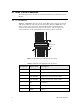
FT 5000 Control Module The following sections describe the electrical interface for the FT 5000 Control Module. JP1 Connector CP3_RXLED 25 23 21 19 17 15 13 11 9 7 5 3 1 FT_NETA MOV_GND IO10 IO8 IO6 IO4 IO2 IO0 SDA_CS1- Figure 1 and Table 2 show the pinout of the JP1 header connector for the FT 5000 Control Module. The I/O pin function names defined in Table 2 are the same as those used in the Series 5000 Chip Data Book, which defines the functions and electrical characteristics for the signals.
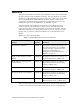
Pin Number Signal Name Description 8 SCL I2C serial clock for in-circuit programming 9 SDA_CS1~ I2C serial data for in-circuit programming 10 SVC~ Service (active low) 11 IO0 IO0 for I/O objects 12 IO1 IO1 for I/O objects 13 IO2 IO2 for I/O objects 14 IO3 IO3 for I/O objects 15 IO4 IO4 for I/O objects 16 IO5 IO5 for I/O objects 17 IO6 IO6 for I/O objects 18 IO7 IO7 for I/O objects 19 IO8 IO8 for I/O objects 20 IO9 IO9 for I/O objects 21 IO10 IO10 for I/O objects
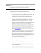
P1 and P2 Connector Terminals Table 3, Table 4 on page 5, and Table 5 on page 5 show the pinout of the P1 and P2 connector terminals for the Neuron 3150 Control Modules. The I/O pin function names defined in Table 3 are the same as those used in the Neuron Chip Data Book, which defines the functions and electrical characteristics for the signal names. The I/O signals are connected directly to the Neuron 3150 Chip without buffering. Table 3.
Table 4. 6-pin Network Connector (P2) for the TP/XF Control Modules Pin Number Name Description 1 CTB Transformer center tap 2 CTA Transformer center tap 3 Data B Network data B signal 4 Data A Network data A signal 5 NC No connection 6 NC No connection Note: CTA and CTB must be shorted together on the applications electronics board. Table 5.
reset pin are described in the Series 5000 Chip Data Book or the Neuron Chip Data Book. Service Pin You can access the service pin (SVC~) of the FT 5000 Control Module at pin 10 of the JP1 header. You can access the service pin (SERVICE~) of the Neuron 3150 Control Module at pin 18 of the P1 header. This pin is used for various network installation and maintenance scenarios. The function of this pin is described in the Series 5000 Chip Data Book or Neuron Chip Data Book.
2 Mechanical Considerations This chapter discusses the mechanical footprint and connectors of the Twisted Pair Control Modules. Details of mounting to an application electronics board are provided.
FT 5000 Control Module The following sections describe the mechanical interface for the FT 5000 Control Module. Floorplan Layout Figure 3 shows three views of the floorplan layout of the FT 5000 Control Module with some of its prominent features labeled. 16 mm (0.63 in) 43.18 mm (1.7 in) 5 AT 24C 512 29.85 mm (1.175 in) FT 5000 C7,17 Y1 6 FT-X3 7 RV1 1 Back View 4 Side View 8 3 2 1 1 Front View Figure 3.
Mechanical Footprint The Neuron 3150 Twisted Pair Control Modules share a common footprint and connectors as shown in Figure 5 on page 10. The most common control module mounting scenario uses socket strips on the application electronics board which connect with P1 and P2 as shown in Figure 6 and Figure 7 on page 11. Example vendor information for socket strips that mate with the 0.025 inch (0.64 mm) square header posts of P1 and P2 are listed in Table 6 on page 11.
Figure 5.
Table 6. Socket Strips Suitable for Use with the Control Module Header Pins Manufacturer P1: 18-pin (2 X 9) P2: 6-pin (1 X 6) Samtec SSW-109-01-T-D SSW-106-01-T-S Methode * 9000-209-303 9000-106-303 Advanced Interconnections BC-009-124TL BC006-123TL * Not recommended for use with the TP/FT-10 or TP/FT-10F Control Modules. Figure 6. Recommended Spacing between the TP/XF-78, TP/XF-78F, and TP/XF-1250 Control Modules and the Application Electronics Board Figure 7.
Figure 8.
Figure 9.
3 Power Requirements This section describes the power requirements for the control modules as well as considerations for noise filtering in order to comply with both conducted and radiated emissions requirements.
FT 5000 Control Module The following sections describe the power requirements for the FT 5000 Control Module. Control Module Power Requirements FT 5000 Control Modules require a +3.3 VDC power source with sufficient current to power the control module in all modes of operation. The supply current requirements for the FT 5000 Control Modules are outlined in Table 7, including typical requirements for the different operating states of the FT 5000 Smart Transceiver at various system clock rates. Table 7.
The supply current requirements for the control modules are outlined in Table 8, which includes peak requirements for the different operating states of the Neuron Chip. The control modules require a 5 V ±5% power supply. The current requirements are characterized for maximum number of devices on the channel with I/O pins programmed as outputs at a logic low level with no load. The values in Table 8 are subject to change. Please consult current data sheets for the latest information. Table 8.
4 Network Cabling and Connection This chapter addresses cabling and termination for the FT 5000 Control Module and the Neuron 3150 Control Modules (TP/FT-10, TP/FT-10F, TP/XF-78, TP/XF-78F, and TP/XF1250 Twisted Pair Control Modules).
Performance Characteristics and Cabling For performance characteristics and cabling information, refer to the sources of information shown in summary Table 9. The specifications shown in Table 9 are provided for convenience only and are not intended to be comprehensive. Table 9.
Wire Characteristics Due to the many cabling and termination options available for the TP/FT-10 channel, please refer to the Series 5000 Chip Data Book, FTT-10 Free Topology Transceiver User's Guide, or FTT-10A Free Topology Transceiver User's Guide, as applicable, for information on wire characteristics and terminations. The Junction Box and Wiring Guidelines for Twisted Pair LonWorks Networks engineering bulletin (005-0023-01) provides a list of cable vendors for each type of supported cable.
is supported per segment, so at least one of the terminations must be the RC-type. TP/XF-78, TP/XF-78F, and TP/XF-1250 The following sections describe the wire characteristics and cabling terminations for TP/XF-78, and TP/XF-1250 channels. In addition, the device distribution rule for TP/XF-1250 network segments is described. Wire Characteristics The Neuron 3150 TP/XF-78, TP/XF-78F, and TP/XF-1250 control modules are designed for distributed control applications using low-cost, Level IV twisted pair wire.
transceivers, or TPM-1250 SMX transceivers to eliminate the possibility of reflection-related transmission failures. No such topology rule applies to the use of TP/XF-78 control modules, TPT/XF-78 transceivers, or TPM-78 SMX transceivers. Referred to as the “8-in-16” topology rule, this rule requires that no more than 8 TP/XF-1250 Control Modules, TP/XF-1250 Transceivers, or TPM-1250 SMX Transceivers be located within any 16 meter length of cable.
Figure 12. Using a Router to Meet the 8-in-16 Topology Rule The second remedy to a violation of the 8-in-16 rule is to add additional cable to the bus such that the rule is no longer violated (see Figure 13). It is important to ensure that the maximum bus length (130 meters of 22 AWG [0.65 mm] Level IV or AWG 24 [0.511 mm] ANSI/TIA/EIA-568-B.2-2001 Category 5 or Category 6 twisted-pair cable) is not exceeded by the additional cable.
Figure 14.
5 Design Issues This chapter describes design issues, including a discussion of Electromagnetic Interference (EMI), and Electrostatic Discharge (ESD), and Designing for Interoperability. This chapter applies to both FT 5000 Control Modules and Neuron 3150 Control Modules.
EMI Design Issues The high-speed digital signals associated with microcontroller designs can generate unintentional Electromagnetic Interference (EMI). High-speed voltage changes generate RF currents that can cause radiation from a product if a length of wire or piece of metal can serve as an antenna. Products that use the Twisted Pair Control Modules generally need to demonstrate compliance with EMI limits enforced by various regulatory agencies.
that grounding and enclosure design questions are addressed early enough to avoid most last-minute changes (and their associated schedule delays). It is possible for a plastic enclosure to be used with Twisted Pair Control Modules in level “B” applications in some specialized configurations.
ground is anywhere within the common ground area around the off-board connections. For a 4-layer PCB, the ground plane serves to distribute ground from the center of the star ground out to the various function blocks in the floorplan. For a 2-layer PCB, ground pours should be placed on the bottom layer (and also on the top layer where possible) in order to connect the grounds of the various function blocks to the center of the star ground.
EMC Keepout Area I/O Circuitry Network Connector FT 5000 Control Module I/O Connectors Center of Star Ground Power Supply Connector Power Supply Circuitry Host Microprocessor (Optional) Figure 15. Example PCB Layout Design for an FT 5000 Control Module Neuron 3150 Control Module Keepout Areas Figure 16 on page 32 shows three “keepout” areas on the Neuron 3150 Control Modules. Area #1, the “EMI Radiated Keepout Area,” covers the Neuron Chip and the PROM.
Figure 16. Control Module Keepout Areas Area #3 is the “High Voltage Isolation Area.” The transceiver coupling transformer on all Neuron 3150 Control Modules provides electrical isolation between the control module’s local ground (primary side) and the network wiring (secondary side). The transformers and associated filter components are designed to withstand moderately large primary-to-secondary voltages (see the control module data sheets for the exact ratings).
Designing Systems for ESD Immunity ESD hardening includes the following techniques: • Provide adequate creepage and clearance distances to prevent ESD hits from reaching sensitive circuitry • Provide low impedance paths for ESD hits to ground • Use diode clamps or transient voltage suppression devices for accessible, sensitive circuits The best protection from ESD damage is circuit inaccessibility.
Figure 17. Example of Diode Clamping Protection for Control Module I/O Lines Designing for Interoperability To meet the LONWORKS interoperability guidelines for the Neuron 3150 TP/XF78, TP/XF-78F, and TP/XF-1250 devices, the following printed circuit layout guideline for the application electronics board is recommended.
6 Programming Considerations This section explains the integration of control modules using the NodeBuilder FX Development tool. It covers considerations relating to memory specifications, device definition, channel definition, and target hardware.
External Memory Considerations The following sections describe considerations for the external memory devices on the FT 5000 Control Module and Neuron 3150 Control Modules. FT 5000 Control Module The FT 5000 Control Module includes an Atmel® AT24C512BN-SH25-T two-wire serial EEPROM to hold the application image.
Table 11. Pin Connections for Aardvark Programmer and JP1 Header Aardvark Programmer Header FT 5000 Control Module JP1 Header Pin Signal Pin Signal 1 ACS_2_SCL 8 SCL 3 ACS_1_SDA 9 SDA_CS1~ 10 ARST~ 2 RST~ The connection between the Aardvark programmer header’s ARST~ signal and the FT 5000 Control Module JP1 connector’s RST~ signal ensures that the FT 5000 Smart Transceiver is held in reset during device programming.
c. Press the Service Pin button on the device to send a service-pin message to the NodeUtil utility. If you cannot receive a servicepin message from the device, repeat steps 1 to 5. d. Within the NodeUtil utility, select the L option to see all connected devices. e. Select the G option to manage the device that just sent a servicepin message. Typically, this is device 1. f. Select W to write to a memory location.
on the control module. The standard TP/XF-78 and TP/FT-10 Control Modules have a 5 MHz input clock, and require a memory access time of 200 ns or faster. The TP/XF-1250 Control Module has a 10 MHz input clock, and requires a memory access time of 90 or 120 ns or faster, depending on the production date of the module. TP/XF-1250 modules produced before January 1995 (revision code A to G) require a 90 ns access time or faster.
Table 13 lists Greenliant parts that you can use as replacements for obsoleted Atmel parts. Table 13.
• Create your own resource files with your UNVTs, UCPTs, and user functional profiles. • Automatically generate Neuron C code that implements your device interface. • Edit your Neuron C code to implement your device functionality. • Compile and build your application, and download it to an Echelon Evaluation Board, Control Module, or to your own devices. • Test with prototype hardware to test your device’s I/O and related hardware.
Table 15.
Configuration for Neuron 3150 Control Modules The NodeBuilder FX Development Tool includes hardware templates for the Neuron 3150 Control Modules. Table 16 and Table 17 on page 44 show the values required for each tab in the NodeBuilder device template editor to support the Neuron 3150 Control Modules. Use these hardware templates as a basis for your device development. Table 16.
Table 17.
Programming The NodeBuilder FX Development Tool generates application image files automatically with each build. After a build is successfully completed using the correct device template file, the next step is to commit the program image to the program memory device using a PROM programmer or an in-circuit programmer.
implements layers 2 to 5 (and part of layer 6) of the LonTalk protocol and provides the physical interface for the LONWORKS communications channel. A simple serial communications interface provides communications between the ShortStack Micro Server and the host processor. Because a ShortStack Micro Server can work with any host processor, you must provide the serial driver implementation, although Echelon does provide the serial driver API and an example driver for a specific host processor.
www.echelon.