LONWORKS® USB Network Interface User’s Guide @ ® 078-0296-01B
Echelon, LNS, LONWORKS, NodeBuilder, LonMaker, LONMARK, Neuron, 3120, 3150, the Echelon logo, and the LONMARK logo are registered trademarks of Echelon Corporation. OpenLDV and LonScanner are trademarks of Echelon Corporation. Other brand and product names are trademarks or registered trademarks of their respective holders.
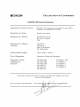
FCC Compliance Statement – Class B This equipment has been tested and found to comply with the limits for a Class B digital device pursuant to Part 15 of the FCC Rules. These limits are designed to provide reasonable protection against harmful interference in a residential installation. This equipment generates, uses, and can radiate radio frequency energy and, if no installed and used in accordance with the manufacturer’s instruction manual, may cause interference with radio communications.
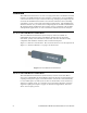
Welcome This document describes how to install and use Echelon’s U10 and U20 USB Network Interface products. The U10 and U20 USB Network Interfaces are lowcost, high-performance LONWORKS interfaces for USB-enabled PCs and controllers. The U10 USB Network Interface connects directly to TP/FT-10 Free Topology Twisted Pair (ANSI/CEA-709.3) LONWORKS channels through a high quality removable connector, and is fully compatible with link powered channels.
• 128MB RAM or more as required by operating system • 10MB of available hard-disk space • Available USB 1.1 or 2.0 port Table of Contents Welcome ........................................................................................................... i Related Documentation .................................................................................. i System Requirements ..................................................................................... i Table of Contents .................
1 Introduction This chapter introduces the USB Network Interfaces, and describes how to install the software included with the USB Network Interfaces.
Overview The USB Network Interfaces are low-cost, high-performance LONWORKS network interfaces for USB-enabled PCs and controllers. Designed for use in LONWORKS control networks that require a PC for monitoring, managing and diagnosing the network, the USB Network Interfaces are ideal for industrial control, building automation, process control and transportation applications.
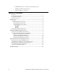
Figure 1.2 shows the U20 interface. The coupling circuit/power supply connection is on the right side of Figure 1.2, and the USB Series “A” plug is on the left side. Figure 1.2 U20 USB Network Interface USB Network Interface LEDs Each USB interface has three LEDs that you can use to determine the interface’s current state. These LEDs become operational as soon as power is applied to the interface’s USB Series “A” plug.
Installing the OpenLDV Software You should install the OpenLDV software before connecting the USB interface to your PC. You must have Administrator privileges on your PC to perform the installation. To install the OpenLDV software, follow these steps: 1. Check that your PC meets the requirements listed in the System Requirements section on page i. 2. Insert the USB Network Interface Drivers CD into a CD-ROM drive. 3. The OpenLDV installer starts automatically. If it does not, run the OpenLDV210.
2 Using the USB Network Interface This chapter describes how to connect your PC to a network channel with a USB interface. It also describes how to configure, test and identify a USB interface with the LONWORKS Interfaces application in the Control Panel.
Connecting the USB Network Interface After you have installed the OpenLDV software, you can plug the USB interface into your PC and connect to a TP/FT-10 or PL-20 channel (as appropriate). To do so, follow these steps: 1. Insert the USB interface into an available USB port on your PC, with or without the included USB extension cable.
into a PC, even after they have been detached from the PC. This means that a particular USB interface will continue to use the same LONWORKS network interface name (e.g. LON1 or LON2) once it has been inserted and recognized by your PC, regardless of how many USB interfaces are plugged into the PC, or in which order. It also means that each USB interface will retain the network interface name assigned to it, even after it has been detached from your PC.
2. Select the USB tab. You will see a list of the USB interfaces that are currently connected to your PC. If there are other non-USB LONWORKS interfaces attached to the PC, the first USB interfaces will not necessarily be named LON1. If you do not see at least one USB interface listed on the tab, consult Appendix B, Troubleshooting. Figure 2.
3. Select the USB interface you want to configure and then click Properties. This opens the dialog shown in Figure 2.2. Figure 2.2 Properties Dialog 4. The Transceiver Type field only applies to U20 interfaces. Select PL20C if you must comply with the European CENELEC EN50065-1 regulations. Select PL-20N if you do not need to comply with these regulations. PL-20N channels offer slightly higher message throughputs than PL-20C channels, so normally you would use PL20N if you can do so.
Table 2.1 describes the default buffer configuration, as well as three other buffer configurations you could consider using. For more detailed information on buffer configurations, see the Allocating Buffers section in Chapter 8 of the Neuron C Programmer’s Guide. Table 2.1 Buffer Configurations Description This is the default buffer configuration. Most users should use this configuration.
Testing a USB Network Interface To test or reset the USB interface, follow these steps: 1. On the USB tab, select the USB interface you want to test and then click Test. This opens the dialog shown in Figure 2.3. NOTE: You can only test a USB interface if it is not in use by another application. Figure 2.3 Test Dialog 2. From the Test dialog, you can perform the following tasks: • Click Test to confirm the ability of an application to communicate with the USB interface.
• Click Service to send a service pin message to the network. • Click Reset to reset the interface. When you reset the interface, the statistic counts retrieved with Test will be set to 0. • Click OK to exit the Test dialog and return to the USB tab. Identifying a USB Network Interface If you have multiple USB interfaces installed on your PC and you need to establish which physical interface is associated with a logical interface name (e.g.
Appendix A Alternate Power Line Coupling Circuit Echelon includes either a US Plug or a Continental Europe Plug wall-plug coupling circuit/power supply with each U20 interface. For specialized applications, you can design your own coupling circuit/power supply, or for 10.8-18VDC systems, you can make a direct connection without any additional coupling.
Alternate Power Line Coupling Circuit This appendix describes how to design a power supply and coupling circuit for the U20 interface. Before attempting to do so, you must carefully read and understand Chapter 4, Coupling Circuits, of the PL 3120 / PL 3150 Power Line Smart Transceiver Data Book. You also need to understand the power requirements of the U20 interface, and the circuitry provided in the U20 interface and wall-plug coupling circuit/power supply. These topics are described in this appendix.
The supplied wall-plug coupling circuit/power supply includes a step-down transformer and a 12uH-leakage coupling transformer. Two diodes are used to rectify the AC on the step-down side of the power transformer. The schematic for the wall-plug power supply is shown in Figure A.2. COUPLING TRANSFORMER COMBINED VA SUPPLY/COUPLING LINE AC INPUT NEUTRAL STEP-DOWN TRANSFORMER Figure A.2 Wall-Plug Supply Schematic You will note the absence of a capacitor on the output of the supply. This is intentional.
VA TX AMP Ferrite Bead RX Front End 2.1mm DC Power Jack RXIN RXCOMP Figure A.3 Coupling Circuit and Power Supply Input Schematic This is the same circuit that is described for the Line-to-Neutral (L-to-N) Isolated Wall-Plug Power Supply/Coupler in the PL 3120 / PL 3150 Power Line Smart Transceiver Data Book.
inductance between the power source and the power line devices. Small EMC capacitors across the line are acceptable as long as they meet the guidelines in Chapter 6, EMC Suppression Capacitor Value vs. Application, of the PL 3120 / PL 3150 Power Line Smart Transceiver Data Book. Custom AC Isolated Coupling For high voltage isolated coupling, you will essentially be building your own custom version of the supplied wall-plug power supply. Refer to this schematic shown in Figure A.
COUPLING TRANSFORMER LINE NEUTRAL >220uH >300mA DCR <1ohm COMBINED VA SUPPLY/COUPLING Figure A.
Appendix B Troubleshooting The USB Network Interface software installed by the OpenLDV Installer is auto-configuring, and the USB Network Interfaces are designed to be the easiest-to-use LONWORKS network interface available on the market. In the unlikely event that a problem occurs, this appendix describes how to diagnose and fix the problem. If the solutions in this appendix do not yield a working USB interface, contact Echelon Support at www.echelon.com/support.
1. I have inserted my USB interface into a USB port on my computer, but the Found New Hardware Wizard has not opened and the computer has not detected the device. What should I do? • Verify that you are running Windows XP, Windows 2000, or Windows Server 2003. • Verify that you have a USB 1.1 or 2.0 host controller on your PC. • Verify that other USB devices that you may have work on this PC. • Verify that the OpenLDV 2.0 or higher software has been installed on this PC.
• If the Device Manager lists Echelon USB Network Interface under the Universal Serial Bus controllers heading, open the USB Network Interface item. If the status indicates that the driver is not working properly, first try repairing the OpenLDV software. If that doesn’t work, download the latest version of the OpenLDV Installer from Echelon’s web site. Both of these options are described above. • Unplug and re-insert the USB interface.