® @echelon CPD 3000 Lighting Controller Integration Guide Version 1 078-0485-01A
Echelon, LONWORKS, LONMARK, and the Echelon logo are trademarks of Echelon Corporation registered in the United States and other countries. Other brand and product names are trademarks or registered trademarks of their respective holders. ECHELON MAKES AND YOU RECEIVE NO WARRANTIES OR CONDITIONS, EXPRESS, IMPLIED, STATUTORY OR IN ANY COMMUNICATION WITH YOU, AND ECHELON SPECIFICALLY DISCLAIMS ANY IMPLIED WARRANTY OF MERCHANTABILITY OR FITNESS FOR A PARTICULAR PURPOSE.
Welcome Echelon’s Power Line based lighting controller, the CPD 3000, can be used to control outdoor street lights which support proportional level control level control using 0-10V or PWM control. In addition to control, the CPD 3000 collects vital data such as run hours, voltage, current, power consumption, energy usage, diagnostic alarms, and power factor. The information collected is shared through communication on the AC mains. The CPD 3000 optimizes communications with integrated power line meshing.
Table of Contents Welcome ......................................................................................................... iii CPD 3000 Installation and Wiring Guidelines ........................................... 5 Installation ..................................................................................................... 6 Wiring Specification and Diagram ................................................................ 7 CPD 3000 Mechanical Dimensions ......................................
1 CPD 3000 Installation and Wiring Guidelines The CPD 3000 Lighting Controller can be installed within the lighting fixture, in the access hold of the lighting fixture pole, in the gear tray, or in a separate box.
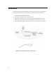
Installation Installation for the CPD 3000 OLC uses the following steps. It is important to disconnect line voltage before installing or replacing a CPD 3000 module. 1. Install the CPD 3000 OLC module. 2. Connect the AC mains power to the module. 3. Connect the filtered power output of the CPD 3000 OLC module to the luminaire power supply (electronic ballast/generator, ballast, or driver). 4. Connect the CPD 3000 control signal wires to the luminaire control input. Figure 1.
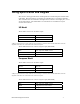
Wiring Specification and Diagram Here are the wiring specifications and diagram for US and European models of the CPD 3000. The CPD 3000 is not suitable for installing above 15,000 feet altitude. The controller must be installed in the light fixture, inside a street light pole, or in a street light cabinet. The CPD 3000 is not intended to be installed in an open outdoor environment.
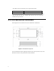
Two AWG 16 wires for filtered power output (both models) Red Line Out Blue Neutral Out or Line 2 Out The 0-10V control signal of the CDP 3000 works with current sourcing inputs. The CPD 3000 will sink up to 1500mA. The filtered switch AC output will handle load up to 500 VA. CPD 3000 Mechanical Dimensions This diagram shows the dimensions of the CPD 3000 in millimeters. Figure 2.
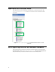
2 CPD 3000 Lighting Controller Interface The CPD 3000 Lighting Controller borrows much of its interface from the SFPToutdoorLuminairController (3512) defined in the LonMark standard resource file set version 13.10. To meet the memory requirements of the PL3120-E4 Smart Transceiver, a specific profile is defined in an Echelon device specific scoped resource file set defined in the DRF files set EchelonLighting.* (Program ID [scope 4] 80 00001 1E00 03 11 03).
Application as Function Block The application for the CPD 3000 is developed as a sole function block. The UFPTlightingController is referred to as the LC in the remainder of this document. Figure 3. UFPTlightingController Funtional Profile Interface used in CPD 3000 UFPTlightingController Network Variables The following table describes the network variables defined for the CPD 3000 implementation of the UPFTlightingController.
Table 1 LC Network UNVTfaults Variables Implemented on the CPD 3000 Network Variable Type Notes nviLampValue SNVT_switch Primary control input. The level translates to a 0-10V control signal with the transform being subject to the values configure in nciControlConfig defined below. By default, 50% results in a 5V control signal to the ballast, driver, or, generator controlled by the CPD 3000. nviStatReset UNVTstatControl Sets/initializes energy, runtime, and error counts.
transactions to capture level control feedback, environmental variables, and alarm conditions. This network variable reflects all of this information in one single-structured data type defined by UFPTcontrolData. Figure 4. UNVTcontrolData(nvoControlData) Fields The fields for UNVTcontrolData are described in table 2. Table 2 nvoControlData Fields (UNVTcontrolData) Field Type power SNVT_power Reflects the instantaneous power consumed by the LC and controlled fixture. (0.
supplyVoltage SNVT_volts Measured supply voltage 0.1V resolution. This value is updated every second. supplyCurrent unsigned long Measured current with 0.01 amp resolution. This value is updated every second. cycleCount SNVT_count Number of operating cycles (ON-OFF). Updated with each transition to OFF. LevelFB SNVT_lev_cont 0.5% resolution 0-100%. Tracks the .value field of nvoLampFb. 0% if the state is 0. faults UNVTfaults Fault bits. Details are provided in the alarms section.
Broadcast Support The CPD 3000 supports the limited broadcast message support implemented on SmartServer 2.1 Firmware (service release 1). Control updates through this mechanism are reflected on the network variable interface (nviLampValue, and nvoLampFb). Note that the nviLampValue data point should not have a defined heartbeat to properly use the broadcast feature. Behavior for reflection in nvoLampFb follows the Use Case Realization described by the LonMark organization at http://types.lonmark.org/index.
nciPowerProfile UNVTpowerProfile Defines the nominal power measured at 5 commanded nviLampValues 0.5%, 25%, 50%, 75%, 100%) while driving the driver/lamp combination. This CP must be set for lowPower/HighPower, and measured with nvoLampFb values to work correctly. They will depend on the minPWM and maxPWM fields defined in the following section. UNVTControlCfg This section describes how the fields in this configuration property are applied in the LC. Figure 5.
CoolDownTm will extend this time.as required when controlling certain lamp types such as HPS. rampTm SNVT_time_sec Controls how the LC ramps between level transitions. Only used after the lamp is ON to go between intermediate steps. The CPD 3000 limits this value to a maximum of 30s. (Default value – 1.5s) supplyVoltage SNVT_volt The nominal supply voltage for the fixture. Used of voltage level alarms. (Default value – 240V).
lower limit of the PWM output with the nviLampValue is at 0.5%. Limit to 0255. (Default value – 0). Use this to limit the low level light setting to maintain efficient operation. maxPWM unsigned long It may be necessary to set the highest 010V signal to a value that can be used to drive the controlled fixture. This value upper limit of the PWM output with the nviLampValue is at 100%. Limit to 0255. (Default value – 255) pwmClock unsigned short Allows programming of the PWM clock.
Working with the CPD 3000 and the target driver/ballast is required to determine the limits for the best scaling of the nviLampValue.value to the actual control signal. These values must be set before the nciPowerProfile initialization can be determined. LC Alarm Management The LC provides rich support for status bits which are derived from the power measurement chip included in CPD 3000 hardware.
controlled to defaultLev (Default –0s; which means HB checking is disabled) nciPowerProfile UNVTpowerProfile Defines the nominal power at 0.5, 25, 50, 75, 100% lamp nviLampValue.value. Used to determine the expected power draw using linear interpolation for nviLampValue.values in between steps defined in the table. nciLimits.powerLowFault SNVT_lev_cont The percentage deviation of expected power below which the LowPower alarm is triggered. (Default value - 15%) nciLimits.
alarm is triggered. (Defaults value - 65.0 C) nciLimits.lampFailFault SNVT_lev_cont The threshold of power drop measured when the lamp fails. In some technologies, induction lights for example, the power draw at bulb failure may be quite high. (Default value - 20%). The field nciControlCfg.clrTm controls when the alarm flags reported in nvoLcStatus will be cleared. In an SLV managed lighting system, alarm logs are scheduled for daily delivery at some point after the sunrise OFF command.
LowSupplyVoltage Measured voltage is nciLimits.voltageLow % below the voltage defined by nciControlCfg.supplyVoltage HighSupplyVoltage Measured voltage is nciLimits.voltageHigh % above the voltage defined by nciControlCfg.supplyVoltage RelayFailed Power measured when the load switch relay is disengaged above 6.0W. This would occur if the relay contacts were to weld shut.
The CPD 3000 uses the nciPowerProfile table to define the expected power at five equally spaced nviLampValue.values (.5%, 25%, 50%, 75%, 100%) once the minPWM and maxPWM CP fields have been established. Note that nviLampValue.state is set to -1 at powerup/reset. CPD 3000 Control Sequence The CPD 3000 implements the state machine diagram depicted in figure 5 below. The field nvoControData.LCstate reports the current active state for the controller.
E WARMUP state timer expires OR commanded OFF Updates to nviLampValue are delayed until out of WARMUP. F COOLDOWN state timer expires AND (.defaultLev > 0 AND rcvTmo) OR command ON Occurs when .warmupTm is > 0 G WARMUP state timer expires AND (commanded ON OR (rcvTmo AND .defaultLev > 0)) H command OFF OR (rcvTmo AND .defaultLev == 0) I .warmupTm == 0 AND (Command ON OR (rcvTmo AND .