Neuron® C Programmer’s Guide ® 0 7 8 - 0 0 0 2 -02 H
Echelon, LONWORKS, LONMARK, NodeBuilder, LonTalk, Neuron, 3120, 3150, ShortStack, LonMaker, and the Echelon logo are trademarks of Echelon Corporation registered in the United States and other countries. 3170 is a trademark of the Echelon Corporation. Other brand and product names are trademarks or registered trademarks of their respective holders.
Welcome This guide describes how to write programs using the Neuron® C Version 2.2 language. Neuron C is a programming language based on ANSI C that is designed for Neuron Chips and Smart Transceivers. It includes network communication, I/O, and event-handling extensions to ANSI C, which make it a powerful tool for the development of LONWORKS® applications. Key concepts in programming with Neuron C are explained through the use of specific code examples and diagrams.
Related Documentation The following manuals are available from the Echelon Web site (www.echelon.com) and provide additional information that can help you develop Neuron C applications for LONWORKS devices: • Introduction to the LONWORKS Platform (078-0391-01A). This manual provides an introduction to the ISO/IEC 14908 (ANSI/CEA-709.
Table 1.
Table of Contents Welcome .........................................................................................................iii Audience ........................................................................................................iii Related Documentation ................................................................................ iv Typographic Conventions for Syntax........................................................... iv Chapter 1. Overview .....................................
Fixed Timers .......................................................................................... 36 Scaled Timers and I/O Objects ............................................................. 37 Calculating Accuracy for Software Timers .......................................... 37 Accuracy of Millisecond Timers ..................................................... 37 Accuracy of Second Timers............................................................. 40 Delay Functions..............................
Instantiation of Configuration Properties .................................................. 88 Device Property Lists ............................................................................ 89 Network Variable Property Lists ......................................................... 90 Accessing Property Values from a Program............................................... 91 Advanced Configuration Property Features ..............................................
The resp_receive( ) Function ........................................................ 139 Format of a Response.................................................................... 139 Request/Response Examples............................................................... 140 Comparison of resp_arrives and msg_succeeds................................. 141 Idempotent Versus Non-Idempotent Requests.................................. 141 Application Buffers .......................................................
Chips without Off-Chip Memory ........................................................ 177 Memory Regions .................................................................................. 177 Memory Areas...................................................................................... 178 Default Memory Usage ....................................................................... 180 Controlling Non-Default Memory Usage ...........................................
Appendix A. Neuron C Tools Stand-Alone Use..............................................211 Stand-Alone Tools ...................................................................................... 212 Common Stand-Alone Tool Use .......................................................... 212 Common Syntax ............................................................................ 212 Common Set of Basic Commands ................................................ 214 Command Switches for Stand-alone Tools ....
1 Overview This chapter introduces the Neuron C Version 2.2 programming language. It describes the basic aspects of the language and provides an overview to using the LONWORKS platform and the Neuron C programming language to construct interoperable devices and systems. The chapter also introduces key concepts of Neuron C such as eventdriven scheduling, network variables, configuration properties, and functional blocks (which are implementations of functional profiles).
What Is Neuron C? Neuron C Version 2 is a programming language based on ANSI C that is designed for Neuron Chips and Smart Transceivers. It includes network communication, I/O, and event-handling extensions to ANSI C, which make it a powerful tool for the development of LONWORKS applications. Following are a few of these new 1 features: • A new network communication model, based on functional blocks and network variables, that simplifies and promotes data sharing between like or disparate devices.
• fb_properties • nv_properties • device_properties • cp • cp_family You can still manually create the self-documentation strings, if necessary, by avoiding the use of any of these keywords and by declaring the selfdocumentation strings using the Neuron C version 1 syntax. Using this syntax could be useful for migrating older applications (created with the NodeBuilder 1.5 or LonBuilder tools) to the NodeBuilder FX Development Tool.
Neuron C is designed to execute in the environment provided by the Neuron system firmware. This firmware provides an event-driven scheduling system as part of the Neuron C language’s run-time environment.
0x0 .. 0x7F 0x80 .. 0xFF 0x100 .. 0x7FFF 0x8000 .. 0xFFFF signed short unsigned short signed long unsigned long Octal constants have the following default types, which can also be modified as described above with the u, U, l, and L suffixes: 0 .. 0177 0200 .. 0377 0400 .. 077777 0100000 .. 0177777 signed short unsigned short signed long unsigned long Binary constants have the following default types, which can also be modified as described above with the u, U, l, and L suffixes: 0b0 ..
Neuron C Storage Classes If no class is specified and the declaration is at file scope, the data or function is global. File scope is that part of a Neuron C program that is not contained within a function or a task. Global data (including all data declared with the static keyword) is present throughout the entire execution of the program, starting from the point where the symbol was declared.
uninit When combined with the eeprom keyword (see below), specifies that the EEPROM variable is not initialized or altered on program load or reload over the network.
Declaration Example Data types typedef unsigned long ULONG; Enumerations enum hue {RED, GREEN, BLUE}; Pointers char *p; Functions int f(int a, int b); Arrays int a[4]; Structures and unions struct s { int field1; unsigned field2 : 3; unsigned field3 : 4; }; In addition, Neuron C Version 2 supports the declarations listed in Table 3. Table 3.
declared with the polled modifier), the new value of the network variable is propagated across the network to all devices with input network variables connected to that output network variable. If the output network variable is not currently a member of any network variable connection, no transaction and no error occurs. Although the propagation of network variables occurs through LONWORKS messages, these messages are sent implicitly.
configuration data. Like network variables, configuration properties also provide a well-defined interface. Each configuration property type is defined in a resource file that specifies the data encoding, scaling, units, default value, invalid value, range, and behavior for configuration properties based on the type. A rich variety of standard configuration property types (SCPTs) are available.
of this feature in Chapter 3, How Devices Communicate Using Network Variables, on page 43, and also in the Neuron C Reference Guide.) An application image for a device created by the Neuron C compiler contains SD information unless the #pragma disable_snvt_si directive is used. (See the Compiler Directives chapter of the Neuron C Reference Guide for more information.) Data-Driven Compared with CommandDriven Protocols Network variables are used to communicate data and state information between devices.
Neuron-Hosted and Host-Based Compilation Compilation for Neuron-hosted devices, that is, devices based on a Neuron Chip or Smart Transceiver as the main processor, use Neuron C to define all aspects of the device’s application: • The application’s interoperable interface, including its set of network variables, configuration properties, and functional blocks, and the selfidentification and self-documentation data • Device configuration information, such as buffer configuration • Application code includ
Differences between Neuron C and ANSI C Neuron C adheres closely to the ANSI C language standard; however, Neuron C is not a "conforming implementation" of Standard C, as defined by the American National Standards Institute committee X3-J11. The following list outlines the major differences between Neuron C and ANSI C: • Neuron C does not support floating-point computation with C syntax or operators.
include file. Other ANSI C library functions, such as file I/O and storage allocation functions, are not included in Neuron C. Consult the Neuron C Reference Guide for a complete and detailed list. • The Neuron C implementation includes three ANSI include files: , , and . • Neuron C requires use of the function prototype feature whenever a call to the function precedes the function definition (see Chapter 2, Focusing on a Single Device, on page 15).
2 Focusing on a Single Device This chapter describes the Neuron C event scheduler and I/O objects. The concepts of predefined events and user-defined events are introduced. Code examples in this chapter illustrate the use of events, I/O and timer objects, and I/O functions.
What Happens on a Single Device? In this chapter, you begin to learn about programming a Neuron Chip or Smart Transceiver by focusing first on a single device. Each Neuron Chip and each Smart Transceiver has standard firmware, called the Neuron firmware, and hardware support that implement a scheduler, timers, and I/O device drivers and interfaces. Series 5000 chips also provide hardware support for interrupts; see Interrupts on page 153 for more information.
In this example above, when the led_timer application timer (definition not shown in this example) expires, the body of code (the task) that follows the when clause is executed to turn off the specified I/O object, io_led (also defined elsewhere in the program). After this task has been executed, the timer_expires event is automatically cleared. Its task is then ignored until the LED timer expires again and the when clause again evaluates to TRUE.
event This expression is either a predefined event (see the following section) or any valid Neuron C expression (which can contain a predefined event). Predefined events as well as expressions are enclosed in parentheses. One or more when clauses can be associated with the same task. task A Neuron C compound statement, consisting of a series of Neuron C declarations and statements, enclosed in braces, which are identical to those found in a Neuron C function definition.
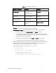
Predefined Event Where Described in This Manual msg_arrives Chapter 6 msg_completes Chapter 6 msg_fails Chapter 6 msg_succeeds Chapter 6 nv_update_occurs Chapter 3 nv_update_completes Chapter 3 nv_update_fails Chapter 3 nv_update_succeeds Chapter 3 offline Chapter 7 online Chapter 7 reset this chapter resp_arrives Chapter 6 timer_expires this chapter wink Chapter 7 A modifier that narrows the scope of the event may follow some predefined events, such as the I/O events and netwo
io_changes). These operators are of equal precedence with each other, but they are mutually exclusive. They are of higher precedence than relational operators (that is, comparisons), but lower in precedence than shift and arithmetic operators.
msg_succeeds msg_fails resp_arrives Most network events, except resp_arrives, are enqueued only if the Neuron C compiler has determined that the application checks for the event. The online, offline, and wink events are always enqueued but are discarded by the scheduler if no corresponding when clause is found. When it reaches the head of the queue, an event remains there until processed by the application.
User-Defined Events A user-defined event can contain assignments and function calls. Such events using complex expressions can affect the response time for all events within a program, so you must minimize calls to complex functions within user-defined events. Assignments within user-defined events can only be done to global variables.
Letter names shown above are used for the clauses in Figure 1 and the following narration of events. This shows how the order of execution of tasks differs from the order the when clauses appear in a program. At the start of this example, no event has occurred, thus no when clause event expression is TRUE. 1 The scheduler begins with A. Since A is FALSE, its task is not executed. 2 Event C occurs and the expression C becomes TRUE. 3 The scheduler moves to B. Since B is FALSE, its task is not executed.
when clause selected evaluates to FALSE, its task is ignored and the scheduler resumes with the first priority when clause. See Figure 14 on page 147. The scheduling algorithm described above can be modified through use of the scheduler_reset pragma, discussed in Chapter 7, Additional Features, on page 145. Important: Excessive use of priority when clauses might starve execution of nonpriority when clauses. If a priority when clause is true the majority of the time, it monopolizes processor time.
void f() { /* body */ } g (a,b) int a; int b; { /* body */ } Although Neuron C can create prototypes, it does not employ the ANSI C Miranda prototype rule. According to the Miranda prototype rule, if a function call does not already have a prototype, a prototype is automatically created for it. In Neuron C, a function prototype is automatically created only when the function is defined. Timers Two types of software timer objects are available to a Neuron C application: millisecond timers and second timers.
initial-value An optional initial value to be loaded into the timer on power-up or reset. Zero is loaded by the Neuron firmware (in other words, the timer is turned off) if no explicit initial-value is supplied.
} If your program has multiple timers, you must include a specific check for each timer so that the expiration event is cleared, as shown below: mtimer x; mtimer y; mtimer z; when (timer_expires(x)) { // task } when (timer_expires(y)) { // task } when (timer_expires(z)) { // task } An alternate style of checking for specific timers is shown below. This example also demonstrates that an event expression is not restricted to use only in a when clause. when (timer_expires) { if (timer_expires(x)) ...
objects can also be linked to Neuron C events, because changes in I/O often affect task scheduling. The Neuron C declaration syntax for I/O objects is described in detail in the I/O Model Reference for Smart Transceivers and Neuron Chips. I/O Object Types Many I/O models are available for Neuron Chips and Smart Transceivers. Certain I/O models are available only for specific chip types, but most are available to all Neuron Chips and Smart Transceivers.
magtrack1 serial wiegand Serial Input/Output Model Types i2c neurowire sci spi • Parallel I/O Models are used for high-speed bidirectional I/O. I/O models within this group use all of the Neuron Chip or Smart Transceiver I/O pins.
options Optional I/O parameters, dependent on the chosen type for the I/O object. The description of each object type includes the type’s available options. Except where noted, these options can be listed in any order. All options have default values that are used when you do not include the option in the object declaration. io-object-name A user-supplied name for the I/O object, in the ANSI C format for variable identifiers.
Example 1: Thermostat Interface This thermostat measures the resistance of a thermistor by measuring the pulsewidth of a waveform that is input to pin IO6. The I/O object declaration is set up to measure the on-time of the waveform. A simple T=mx+b scaling of the on-time yields the temperature. ontime The example also uses a shaft encoder generating a quadrature input as a dial to select a new temperature setting (see Figure 2). The quadrature input object type is used with the io_update_occurs event.
// Uses a thermistor to measure temperature, and a // quadrature encoder to enter setpoint. Activates either // heating or cooling equipment via bit outputs. ///////////////// Include Files ////////////////// #include
desiredTemp = max(DESIRED_TEMP_MIN, desiredTemp); } //////////////////////////////////////////////////////// // Timer task -- execute control algorithm // A timer is used to decide periodically whether to // activate heating or cooling. The temperature comparison // is done only every five minutes to prevent cycling the // equipment too frequently. There are two digital outputs: // one for activating the heating equipment, and one for // activating the cooling equipment.
value through the built-in variable input_value. Dimmer Switch Zero-Crossing Detector 110VAC Neuron Chip IO_6 IO_0 Triac Trigger Shaft Encoder IO_4 IO_5 Figure 3. Simple Dimmer Device // DIMMER.
// since a lower value means more light. currentBrightness -= input_value; // Look for underflow or overflow if (currentBrightness < MAX_BRIGHTNESS) currentBrightness = MAX_BRIGHTNESS; else if (currentBrightness > MIN_BRIGHTNESS) currentBrightness = MIN_BRIGHTNESS; // Change the triac setting to the // desired brightness level io_out(ioLampTriac, currentBrightness); } Example 3: Seven-Segment LED Display Interface The following example shows how to connect multi-character displays to the neurowire port.
+5V C4 3 Digit LED Display .01 F U3 MC14489 Neuron Chip 3 11 IO_8 IO_9 12 18 10 IO_2 8 14 470 R10 7 A 6 B CLOCK 5 C DATA IN 4 D DATA OUT 2 E ~ENABLE 1 F RX 20 G 19 Vss H 9 BANK 1 13 BANK 2 15 BANK 3 16 BANK 4 17 BANK 5 Vdd Multi-Character LED Display Driver Figure 4.
• Triac pulse timer. Timer used to generate pulses for the stretchedtriac and triac output objects. The following timers are implemented in software and have periods that are independent of the Neuron Chip or Smart Transceiver input clock. The accuracy of these timers is discussed in the next section. • Application second timer (that is, an stimer declared in a Neuron C program). • Application millisecond timer (that is, an mtimer declared in a Neuron C program).
Series 3100 device with a 10 MHz clock, the expected duration of a millisecond timer is: E = 0.8192 * floor((D/0.82) + 1) where D is the specified duration for the timer. For example, for a timeout of 100 ms, E equals 99.94 ms.
treats as 820 microsecond ticks. This means that a timer duration is actually 0.999 times the specified duration. For example, for a Series 3100 device with a 2.5 MHz clock, a specified timeout of 99 ms would result in an expected duration of 96.67 ms. The complete formulas for calculating the low and high durations are: L = E - (11*S + 1) H = E + (11*S + 1) The high duration with a 2.5 MHz clock and a specified timeout of 99 ms would thus equal 141.67 ms; the low duration is 51.67.
H1 E1 E1 L1 H2 E2 L2 Time started here. Timer expires in this range. Second iteration of timer expires in this range. Figure 5. Expected, Low, and High Duration of Timeout Events Accuracy of Second Timers The second timers rely on the one-second timer, which is based on the millisecond timer mechanism described earlier. A one-second timer of duration D times out in the range of D-1 to D seconds, where “second” is defined as 1001 milliseconds using the millisecond timer duration formulas for L and H.
count A value between 1 and 33,333. See the Neuron C Reference Guide for the formula used in determining the duration of the delay. Values in the range 33,334 .. 65,535 can be specified, but cause a watchdog timer reset. Example: when (io_changes(io_switch)) { delay(400); // wait 10msec for debounce . . . } The msec_delay( ) function produces a delay of a fixed number of milliseconds independent of the input clock speed.
3 How Devices Communicate Using Network Variables This chapter discusses how LONWORKS devices communicate with each other using network variables. It includes a detailed discussion of how to declare network variables and how network variables on different devices are connected to each other. The use of synchronous network variables, the process of polling network variables, authenticated network variables, and network variables that implement a changeable type are also described.
Major Topics LONWORKS devices communicate with other LONWORKS devices through network variables or application messages. This chapter focuses on network variables, which provide an open interoperable interface, simplify programming and installation, and also reduce program memory requirements. Most Neuron C programs use network variables. Application messages can be used, if required, as described in Chapter 6, How Devices Communicate Using Application Messages, on page 117.
• Changeable-Type Network Variables on page 68 describes how to implement network variables that allow their type to be changed at installation time. Overview As described in Chapter 1, Overview, a network variable is an object that represents a data value and may be connected to multiple devices on a network. How many network variables a Neuron-hosted device can support depends on the device’s memory map, the system firmware, and the development tool version, as shown in Table 6. Table 6.
Figure 6. Sample Development Network with Five Devices The declarations for these two network variables, which appear in different programs, are the following: network output SNVT_switch nvoSwitch; and network input SNVT_switch nviLamp; Behavior of Writer and Reader Devices A writer device can change the value of a network variable. The connected network variables in all reader devices are then updated to reflect this change. In general, a reader device only reads from its copy of the network variable.
Note: This discussion uses the terms writer device and reader device. A writer device is a device that writes to a particular network variable (an output network variable). A reader device is a device that reads a particular network variable (an input network variable). In many cases, a device has both input and output network variables declared in its program, and therefore acts both as a “writer device” and a “reader device,” depending on the network variable.
After the device design is complete, you specify connections between network variable outputs and inputs on different devices. This is discussed in Connecting Network Variables on page 49. The specification of the desired connections is used by a network tool to generate the appropriate network addresses. When these addresses are downloaded into the devices, they ensure that updates sent by writers reach all of the intended readers.
network input SNVT_temp nviTemp; network output SNVT_switch nvoHeater; network output int nvoCurrentTemp; Examples of priority network variable declarations are shown below: network output SNVT_alarm bind_info(priority) nvoFireAlarm; network input boolean bind_info (priority(nonconfig)) nviFireAlarm; An example of declaring a network variable using the unacknowledged service is the following: network output SNVT_lev_cont bind_info(unackd) nvoFillLevel; The unacknowledged service can be used for this network
Figure 7. A Simple Closed-Loop System Use of the is_bound( ) Function A typical application need not know where local output network variables are connected, and need not know the source of updates to local input network variables. While such detail is available where necessary, typical applications can focus on the semantics of the input network variable update and the local control algorithm.
Network Variable Events Chapter 2, Focusing on a Single Device, on page 15, introduced the event scheduling mechanism and discussed a number of predefined events. Four predefined events are specifically related to network variables: nv_update_completes [(network-var-reference)] nv_update_fails [(network-var-reference)] nv_update_occurs [(network-var-reference)] nv_update_succeeds [(network-var-reference)] The nv_update_occurs event applies only to input network variables.
io_out(ioLED, nviLampState.state); } In the following example, when a thermostat device receives a new temperature setpoint, it checks the current temperature and turns the heater on or off if necessary: network input SNVT_temp nviSetpoint; network output SNVT_switch nvoHeater; network output SNVT_temp nvoCurrentTemp; when (nv_update_occurs(nviSetpoint)) { nvoHeater.
heater_failed = FALSE; // heater device received update } The nv_update_completes Event The nv_update_completes event evaluates to TRUE whenever an output network variable update or poll either succeeds or fails. An example of testing for network variable update completion is shown below: #include
Declaring Synchronous Network Variables To declare a synchronous network variable, include a synchronized or sync keyword in its declaration. An example declaration is shown below: network output sync SNVT_temp nvoRelativeTemp; In the following example, the network variable is declared as synchronous so that all the updates are sent. (If more than one alarm goes off, we want to receive notice of all alarms, not just the most recent one.
Preemption Mode The scheduler enters preemption mode when a synchronous output network variable update occurs and there is no application output buffer available. Because the system must send out the synchronous output network variable update, it processes completion events, incoming msg_arrives or nv_update_occurs events, and response events until an application output buffer becomes available. Other events are not processed, unless the when clause for the event is preceded by the keyword preempt_safe.
2 Check for the failure and the success events (nv_update_fails, nv_update_succeeds). 3 Check for the update completion event (nv_update_completes). For example, the following is an acceptable strategy within a program containing three network variables: • Network Variable 1: Program checks for no completion events. • Network Variable 2: Program checks for failure and success. • Network Variable 3: Program checks for update completion only.
The reader device makes its request through the poll( ) function. The syntax is shown below: poll ([network-var]); network-var is an input network variable identifier. If no network variable is specified, all input network variables for the device are polled. For Neuron-hosted applications, an explicit polled declaration is not allowed for an input network variable; see Declaring an Input Network Variable as Polled on page 58.
mtimer tDelayedPolling; /////////////////////////// Tasks ////////////////////// // NV update task -- handle update to lamp state // Use the network variable’s value as the new state // for the lamp when (nv_update_occurs(nviLampState)) { io_out(ioLED, nviLampState.value && nviLampState.state ? LED_ON : LED_OFF); } when (reset) { // set up timer for delayed power-up polling: tDelayedPolling = 4ul * random(); // >= 1 second ...
Example: A lamp and switch example could also be written to use explicit polling of the switch network variable. Complete programs illustrating polling are shown below. Listing 1. Lamp Program Using Polling // LAMP.
IO_4 input bit ioButton = BUTTON_UP; /////////////////////////// Tasks ////////////////////// // I/O task -- handle pushbutton down event // Just toggle the network variable (nvoSwitchState). // In this case, no message is sent until a poll request // is received from a reader device when (io_changes(ioButton) to BUTTON_DOWN) { // button pressed, so toggle state nvoSwitchState.state = !nvoSwitchState.state; nvoSwitchState.value = nvoSwitchState.state ? 200 : 0; } when (reset) { io_change_init(ioButton); ...
Example: network output SNVT_temp nvoTemp; when (timer_expires(heartbeat)) { propagate(nvoTemp); } The propagate( ) function can also be useful where pointers are used to update output network variables. For example, assume that some function, f( ), calculates a complicated set of values and places them in a network variable structure. Assume the function is designed to operate on several similar such variables within a device, thus the function is passed a pointer to each variable.
Initial Value Updates for Input Network Variables Many applications react not only to physical inputs received through I/O models and peripheral hardware, but also respond to input network variable values. For those devices, power-up (and post-reset) behavior must be carefully considered.
Example: network input SNVT_temp nviCurrent; network input SNVT_temp nviSetpoint; network output SNVT_volt nvoValve; eeprom uninit SNVT_temp lastGoodCurrent, lastGoodSetpoint; when(nv_update_occurs(nviCurrent)) { lastGoodCurrent = nviCurrent; nvoValve = algorithm(lastGoodCurrent, lastGoodSetpoint); } when(nv_update_occurs(nviSetpoint)) { lastGoodSetpoint = nviSetpoint; nvoValve = algorithm(lastGoodCurrent, lastGoodSetpoint); } • After power-up or reset, track which network variable has been updated, and e
poll(nviSetpoint); } when(nv_update_occurs(nviSetpoint)) when(nv_update_occurs(nviCurrent)) { nvoValve = control_algorithm(nviCurrent, nviSetpoint); } While this straight-forward solution is adequate for many devices, it is not without problems: • The multi-NV polling approach still needs to ensure that all input network variables have been updated prior to computing a new output value.
Monitoring Network Variables A monitoring device is a LONWORKS device that receives data from many other devices. For example, an alarm display device may monitor many alarm sensor devices. The sensor devices could all have a network variable output declared as a SNVT_alarm output, and the monitor device could have a network variable input, declared as a SNVT_alarm input. Typically, the monitor device waits for a change to its input network variable.
Following is an example for the code on a network monitor device: Example: network input SNVT_alarm nviAlarm; SNVT_alarm alarm_value; nv_in_addr_t alarm_device_addr; when (nv_update_occurs(nviAlarm)) { alarm_device_addr = nv_in_addr; alarm_value = nviAlarm; // Process alarm_device_addr and alarm_value // Look up alarm_device_addr in a configuration // property set by a plug-in at installation time } This method is appropriate for any number of devices.
Declaring Authenticated Variables and Messages For network variables, include the authenticated (or auth) keyword as part of the connection information. The partial syntax is shown below. For complete syntax of the bind-info clause, see the Neuron C Reference Guide. bind_info ( authenticated [(config | nonconfig)] ) Note: The authenticated keyword can be abbreviated as auth. Likewise, the nonauthenticated keyword can be abbreviated as nonauth.
4 Device B compares its computed transformation with the number it receives from Device A. If the two numbers match, the identity of the sender is verified, and Device B can perform the requested action and send its acknowledgment to Device A. If the two numbers do not match, Device B does not perform the requested action and an error is logged in the error table.
You can use a changeable-type network variable to implement a generic functional block that works with different types of inputs and outputs. For example, you can create a general-purpose device that can be used with a variety of sensors or actuators, and then create a functional block that allows the integrator to select the network variable type depending on the physical sensor or actuator attached to the device during installation.
configuration property access through LW-FTP and check, in the stop_transfer( ) function, whether the SCPTnvType value has been modified. Alternatively, you can implement the SCPTnvType configuration property as a configuration network variable and check the current type in the task for the nv_update_occurs(cpnv-name) event. For example, the following code declares a changeable-type output network variable with its SCPTnvType configuration property.
property automatically assumes the size and type of the network variable it applies to, and is governed by the same initial type and maximum size. Processing Changes to a SCPTnvType CP When a plug-in or the LonMaker browser changes the type of a network variable, it informs your application of the change by writing a new value to the SCPTnvType configuration property associated with the network variable.
Validating a Type Change There are several ways that your application can determine if it supports a particular SCPTnvType value. It can look for specific types, as specified by the type_program_ID, type_scope, and type_index fields. Alternatively, it can look for specific type categories, as defined by the type_category and type_length fields. The type_program_ID and type_scope values specify a program ID template and a resource scope that together uniquely identify a resource file set.
If one or more type-inheriting configuration properties apply to changing configuration network variables (CPNVs), these type-inheriting CPNVs also change their type at the same time. If this type-inheriting CPNV is shared among multiple network variables, all related network variables must change to the new type. Sharing a type-inheriting configuration property among both changeable and non-changeable network variables is not supported.
Your application must always support the NVT_CAT_INITIAL type category. If the requested type is of that category, your application must ignore all other content of the SCPTnvType configuration property and change the related network variable’s type back to its initial type. The network variable’s initial type is the type the network variable was declared with in Neuron C (SNVT_volt_f in the earlier example).
The get_nv_length_override( ) function returns the current length of the network variable with the index specified in the argument, or 0xFF to indicate that the type has not been changed and the network variable’s initial length is still valid. The system image extension method only works with version 14 firmware, or newer. To support development of applications that use the best possible method depending on the target hardware, you can use conditional compilation to support both methods.
of the framework provided by NodeBuilder Code Wizard. Your application might not contain those functions, and you should consider providing equivalent functionality in that case. Parts of the example below are shown in boldface type. This indicates the most important parts of the example. The rest of the code (non-boldface type) can be considered more detail-oriented on first read-through. #include #include #include #include
// and allow for its use even if the target device doesn't support // system extensions. See text for details, and see the Neuron C // Reference Guide, Compiler Directives, for details about these // directives. #pragma system_image_extensions nv_length_override #pragma unknown_system_image_extension_isa_warning // see text! // // // // // // // // changeLength() performs or rejects the type change request.
#endif // // // // For all inheriting configuration properties that apply to this network variable and that are implemented as configuration network variables, repeat this type change. break; case NVT_CAT_INITIAL: // // // // // // // // // This is a request to change the type back to its initial type (whichever is the initial type).
// returns the current length of the given NV (in bytes) or 0xFF to // indicate that the initial type is still unchanged. unsigned get_nv_length_override(unsigned uNvIndex) { unsigned uResult; uResult = 0xFF; if (uNvIndex == fbSensor::nvoValue::global_index) { // Return current length for our example NV, or return // 0xFF to indicate the NV has the initial length: if (nvTypeLastGood.type_category != NVT_CAT_INITIAL && nvTypeLastGood.
// // // // // // // // // // TODO: If needed by the application algorithm, transform the raw *pFloat NV value into the scaled float equivalent using the following formula: scaled = A * 10**B * (*pFloat + C) Scaling factors are accessible via the scaling_factor_X members of the SCPTnvType CP, for example nvo1::nvType.scaling_factor_a. This transformation is a costly operation and it is recommended to design the application algorithm such that this conversion is not required at all, if possible.
// for details. nvoVolt = nvLocal.
4 Using Configuration Properties to Configure Device Behavior This chapter discusses the declaration and use of configuration properties. Configuration properties are part of the device interface, and are used by network tools to configure device behavior during and after network installation.
Overview A configuration property is a data item that, like a network variable, is part of the device’s interoperable interface. A configuration property can be modified by a network tool. Configuration properties facilitate interoperable installation and configuration tools by providing a standardized network interface for device configuration data. Like network variables, configuration properties also provide a well-defined interface.
configuration file, and no events are automatically generated when a configuration property implemented within a configuration file is updated. The application can force notification of updates by requiring network tools to reset the device, disable the functional block, or take the device offline when a configuration property is updated (though the reset or online notification is the only type of notification that occurs after the configuration property has been modified).
configuration property, or with the entire configuration network variable array being handled as a single configuration property. See Instantiation of Configuration Properties on page 88 for details. A configuration network variable's declaration can contain an initial-value or an initializer-list, like any other network variable declaration, as discussed in the previous chapter. Unlike any other network variable, a configuration network variable cannot, itself, also have a network variable property list.
in the standard.typ file, which is part of the standard resource file set included with the NodeBuilder tool. There can be many similar resource files containing UCPT definitions, and these are managed by the NodeBuilder Resource Editor as described in the NodeBuilder User’s Guide. A configuration property type is similar to an ANSI C typedef, but it is also much more. The configuration property type also defines standardized semantics for the type.
4 If the configuration property type for the configuration property defines a default value, then that default value is used as the initial value. This rule does not apply for a configuration property type that is typeinheriting; see Type-Inheriting Configuration Properties on page 98. 5 If no initial value is available from any of the preceding rules, a value of all zeros is used. The cp_family declaration is repeatable.
identify the association between the configuration property and the object or objects to which it applies. Device Property Lists A device property list declares instances of configuration properties defined by CP family declarations and configuration network variable declarations that apply to a device. See the Neuron C Reference Guide for the device-property syntax. Example: SCPTlocation cp_family cpLocation; device_properties { cpLocation = { "Unknown" } }; The device property list appears at file scope.
A Neuron C program can have multiple device property lists. These lists are merged together by the Neuron C compiler to create one combined device property list. However, you cannot have more than one configuration property of any given SCPT or UCPT type that applies to the device. If two separate modules specify a particular configuration property of the same type in the device property lists, this situation causes a compilation error.
member that is shared between two or more network variables. The use of the static keyword creates a CP family member that is shared between all the members of a network variable array, but not with any other network variables outside the array. See Sharing of Configuration Properties on page 96 for more information on this topic. Accessing Property Values from a Program You can access configuration properties from a program just as you can access any other variable.
Since the same CP family could also be used as a device property, there is a special context defined for the device. The device’s context is a context operator (two consecutive colon characters) without a preceding context identifier. Example, Accessing a Device Property: network input SCPToemType cp cpOemType[3]; device_properties { cpOemType = { "Label 1", "Label 2", "Label 3" } }; void f(void) { if (strcmp(::cpOemType[0].ascii, "Demo") == 0) { ... // special demo mode } else { ...
network output SNVT_volt nvoVoltage[4]; Now, suppose that we want to provide a SCPTmaxSendTime configuration property for each sensor output that is used to configure the maximum amount of time (in seconds) between consecutive updates of the output network variable. If we use a configuration property family, we can use the following declarations.
scenario, where part of the configuration property network variable array is used for one array of output network variables, and the other is used for another array of output network variables. Although this case shows all members of the cpMaxSendTime array being used, that is not a requirement.
Initialization of Configuration Properties at Instantiation You can initialize a configuration property of fixed type in its declaration. When a network variable array is used as an array of configuration properties, the following example could occur. Each of the four configuration properties shown below is initialized to the value '10' (a power-up delay value is a number of seconds).
network output SNVT_amp nvoB nv_properties { nciPwrUpDly[1] }; network output SNVT_count nvoC[2] = {100, 100} nv_properties { nciPwrUpDly[2] }; Some configuration property types (for example, SCPTdefOutput) are typeinheriting. This means that the SCPT definition does not, itself, specify the data type for the configuration property. Instead, the configuration property's data type is inherited from the network variable to which it applies.
static cpMaxSendT // Shared among the array // elements only }; Although the discussion above concerns instantiation and shared CP family members, configuration network variables can also be shared using a similar method. Use the static keyword in the array's property list to share a configuration network variable among members of a network variable array. Use the global keyword in the configuration network variable’s property list to share the property among two or more network variables.
requirements of all individually listed FPT members (for example, same type, same array size, and so on). 9 A single configuration property that inherits its type from a network variable cannot be shared simultaneously by both changeable and nonchangeable network variables. Type-Inheriting Configuration Properties You can define a configuration property type that does not include a complete type definition, but instead uses the type definition of the network variable to which it applies.
functional profile is an example of a functional profile that lists the SCPTdefOutput configuration property as an optional configuration property, and it is used to define the default value for the sensor's principal network variable. The SFPTopenLoopSensor functional profile itself, however, does not define the type for the principal network variable. The following example implements a SFPTopenLoopSensor functional block with an optional SCPTdefOutput configuration property.
responsibility of the network tool to apply the formatting rules that apply to the new type when reading or writing this configuration property. The network tool must also set any type-inheriting configuration properties to reasonable initial values that correspond to the new type of the network variable (and thus, the newly inherited type of the configuration property).
5 Using Functional Blocks to Implement a Device Interface This chapter discusses the use of functional blocks to provide a task-oriented interface for a device. You can use functional blocks to group network variables and configuration properties that perform a task together.
Overview The device interface for a LONWORKS device consists of its functional blocks, network variables, and configuration properties. A functional block is a collection of network variables and configuration properties, used together to perform one task. The network variables and configuration properties contained within a functional block are called the functional block members. Using functional blocks promotes modular device design, and focuses the integrators on the control algorithm.
defined by the functional profile – these are called implementation-specific network variables and configuration properties. For example, Figure 10 illustrates standard functional profile number 3050, the Constant Light Controller profile. This profile defines two mandatory inputs, one mandatory output, and one optional input. It also defines one mandatory configuration property and eight optional configuration properties. Figure 10.
and some required data structures that implement a functional block. Principally, the functional block creates associations among network variables and configuration properties. The compiler then uses these associations to create the self-documentation (SD) data and self-identification (SI) data in the device and in its associated device interface file (.xif extension).
Example: network output SNVT_amp nvoAmpere; fblock SFPTopenLoopSensor { nvoAmpere implements nvoValue; } fbAmpereMeter; A Neuron C program can also implement additional network variables in the functional block that are not in the lists of mandatory or optional members of the profile. Such additional network variable members beyond the profile are called implementation-specific members.
added per line. In this way, a functional block can contain an NV array with the elements declared as consecutive NV members. At the end of the member list there is an optional item that permits the specification of a director function. The director function specification begins with the director keyword, followed by the identifier that is the name of the function, and ends with a semicolon.
to provide language-dependent names for your functional blocks. The external name is discussed in more detail in the Neuron C Reference Guide.
Shared Functional Block Properties Just as network variable properties can be shared, functional block properties can be shared between two or more functional blocks. The global keyword creates a configuration property member that is shared among two or more functional blocks. This global member is a different member than a global member shared among network variables.
fb_properties { cpGain, static cpUpdateRate, global cpBypassTime }; fblock SFPTopenLoopSensor { nvoVolt[0] implements nvoValue; } fbVoltMeter[NUM_PHASES] external_name("AmpereMeter") fb_properties { cpGain, static cpUpdateRate, global cpBypassTime }; Scope Rules When adding implementation-specific network variables or configuration properties to a standard or user functional profile, you must ensure that the scope of the resource definition for the additional item is numerically less than or equal to the s
1 Use the NodeBuilder Resource Editor to create a user functional profile with the same functional profile key as the standard functional profile that you want to inherit from. 2 Set Inherit Members from Scope 0 in the functional profile definition. This setting makes all members of the standard functional profile part of your user functional profile. 3 Add your additional members to the new user functional profile. 4 Declare a functional block based on the new user functional profile.
This expression uses the network variable’s member identifier, not the network variable’s unique name. Using the context expression to identify a member network variable therefore promotes modular device design and reuse of code – multiple functional blocks implementing the same functional profile can all implement the same network variable members, although each block’s members are mapped to a different network variable.
// reference of CP family, not CP family member cpGain.multiplier = 123; // '::' instead of '.' fbAmpereMeter[0]::cpGain[i]::multiplier = 123; Neuron C also provides some built-in properties for a functional block. The builtin properties are shown below (the fb-context syntactical element is defined above): fb-context :: global_index fb-context :: director ( expr ) The global_index property is an unsigned short value that corresponds to the global index assigned by the compiler.
between the internal and external names of configuration properties, you should preserve some degree of similarity between the internal and external names. Example: SCPTbrightness cp_family cpBrightness; This example above implements a configuration property family with the internal name cpBrightness of type name SCPTbrightness. The type name is likely to appear as an external, textual, reference to that property, depending on the implementation of the network tool.
Node Object implementation can then direct this request to code specific to the requested functional block by calling the functional block’s director function. The director function provides an easy way for the device to manage its functional blocks and make sure that events and commands are directed to the proper functional block. Example: An implementation of the SFPTnodeObject functional block receives requests through the nviRequest mandatory member network variable input.
fblock_director(nviRequest.object_id, nviRequest.object_request); } } Likewise, a single task can handle all network variable updates by notifying the director function that is in charge of the functional block to which the network variable update applies: #define CMD_NV_UPDATE 17 when (nv_update_occurs) { fblock_director(fblock_index_map[nv_in_index], CMD_NV_UPDATE); } There are no limitations on how you use a director function or how you interpret the second parameter to the director function.
116 Using Functional Blocks to Implement a Device Interface
6 How Devices Communicate Using Application Messages This chapter describes the use of application messages, which can be used in place of or in addition to network variables. The request/response mechanism, a special use of application messages, is also described. Other topics covered include preemption mode, asynchronous and direct event processing, the use of completion events with messages and with network variables, and authentication for messages.
Introduction to Application Messages Application messages are used for creating a proprietary interface (that is, noninteroperable) to a device. The same mechanism used for application messaging can also be used to create foreign-frame messages (for proprietary gateways) and explicitly addressed network variable messages. There is one interoperable use for application messages, and that is the LONWORKS file transfer protocol (LW-FTP).
Layers of Neuron Software When you use network variables in a program, the actual building and sending of messages takes place behind the scenes. This is called implicit messaging. As shown in Figure 11, three layers of software are involved: the application layer (which includes the scheduler), the network layer, and the Media Access Control (MAC) layer.
Application Messages You can explicitly create a message using Neuron C. Rather than using the implicit messaging capability provided by network variables, you can manually construct and send a message. This type of message is called an explicit message. You must identify the type of this explicit message using a message code. The message code identifies the message as an application message, foreign-frame message, or network variable message.
and one incoming message (or response) at any one time. For example, you cannot build up two messages in parallel and send them both. Nor can you parse two input messages at the same time.
the message does not need to be authenticated. The default is FALSE (that is, not authenticated). service Specifies one of the following: ACKD (the default) - acknowledged service with retries REQUEST – request/response protocol UNACKD - unacknowledged service UNACKD_RPT - repeated service (message sent multiple times) Note: Do not use unackd or unackd_rpt in combination with authenticated messages. Use only the ACKD or REQUEST service type.
It might not always be possible to determine rate_est and max_rate_est. For example, message output rates are often a function of the particular network where the device is installed. These optional values can be used by a network tool to perform network device analysis. Although any value in the range 0-18780 can be specified, not all values are used. The values are mapped into encoded values n in the range 0-127. Only the encoded values are stored in the device's self-identification (SI) data.
Type of Message Message Code Description Responder Offline 63 (0x3F) Used by application message responses. Indicates that the sender of the response was in an offline state and could not process the request. Foreign Frames 64 to 78 (0x40..0x4E) Used by application-level gateways to other networks. The interpretation of the message code is left to the application. Foreign Responder Offline 79 (0x4F) Used by foreign frame responses.
Example block transfer of data: msg_tag motor; #define MOTOR_ON 0 typedef enum { MOTOR_FWD, MOTOR_REV } motor_dir; struct { long motor_speed; motor_dir motor_direction; int motor_ramp_up_rate; } motor_on_message; when(some_event) { msg_out.tag = motor; msg_out.code = MOTOR_ON; motor_on_message.motor_direction = MOTOR_FWD; motor_on_message.motor_speed = 500; motor_on_message.motor_ramp_up_rate = 100; memcpy(msg_out.
void msg_cancel(void); This function cancels the message being built for the msg_out object and frees the associated buffer, allowing another message to be constructed. It has no parameters, and has no return value. If a message is constructed but not sent before the task is exited, the message is automatically canceled. The first write operation to the msg_out object triggers automatic, implicit, buffer allocation.
{ // Do nothing, just discard it } To prevent the incoming message queue from becoming blocked, a program that receives application messages, such as that shown in Listing 3, should contain a default when clause with an unqualified msg_arrives event as shown in the example. This is explained further in Importance of a Default When Clause on page 128.
Important: Assigning values to the msg_out object can invalidate fields in the msg_in object. After receiving a message, you must examine or save any necessary fields in the msg_in object before starting to send a message. code A numeric message code. See Message Codes on page 123. len The length of the message data. data The application data. This field is valid only if len is greater than 0.
If a message were to arrive and the application fail to process it, that message would remain at the head of the queue forever, blocking the arrival of any other messages or network variable events and locking up the device until it is reset. One example of a message that would be sent to all devices, most of which are not interested in the message, is the service pin message. Probably only a network tool would want to process the service pin message; all other devices need to discard the message.
#define OFF 0 #define ON 1 // I/O Declaration IO_4 input bit io_switch_in; // Message tag declaration msg_tag TAG_OUT; // Event-driven code when (reset) { io_change_init(io_switch_in); } when (io_changes(io_switch_in)) { // Set up message code based on the switch state msg_out.code = (input_value == ON) ? LAMP_ON : LAMP_OFF; // Set up message tag and send message msg_out.tag = TAG_OUT; msg_send(); } Connecting Message Tags Every device has a default msg_in input message tag.
See Message Tags on page 122 for a more detailed discussion of the nonbind option. The use of explicit addressing has an effect on the buffer sizes needed by the Neuron firmware. See Table 14 on page 196 for more detailed information. You can send network variable updates using explicit addressing by creating an explicit message that corresponds to a network variable update and explicitly setting the destination address.
the event. See the Predefined Events chapter in the Neuron C Reference Guide for more information. The msg_completes event is the most general event. When an outgoing message completes (that is, succeeds or fails), this event evaluates to TRUE. The msg_succeeds event evaluates to TRUE when a message is successfully sent. The msg_fails event evaluates to TRUE when a message fails to be sent (after all retry attempts).
Processing Completion Events for Messages When you send a message, you can optionally check the completion event. Several restrictions apply, however, if you do check the completion event. First, if you check for either msg_succeeds or msg_fails, you must check for both events. The alternative is simply to check for msg_completes. Second, if you qualify a completion event with a particular message tag, then you must always process completion events for that message tag.
msg_send(); } when (msg_fails(TAG1)) { failures[0]++; } when (msg_fails(TAG2)) { failures[1]++; } when (msg_succeeds) { success++; } // any message qualifies Preemption Mode and Messages The Neuron firmware enters preemption mode when there is no application buffer available for an outgoing message.
{ // build a message // send the message } when (msg_completes) { msg_out.tag = t; msg_out.code = 1; // // // // // // This sequence is not recommended. Causes a device reset if the system is already in preemption mode } Instead of using this sequence, build messages and call msg_send( ) in a task with a when clause that does not use the msg_completes event.
The following example indicates one way asynchronous and direct processing cannot be combined. Do not include message completion events in a task associated with a message completion event clause: when (msg_completes) { post_events(); if (msg_completes) x = 4; } // not recommended You can use asynchronous event processing in programs that also do direct event processing. Asynchronous event processing is the typical method for processing events. This method results in smaller application programs.
Important: Because an Interoperable Self-Installation (ISI) network uses unbounded groups (group size 0), your ISI-enabled application should not poll network variable values. Using a request/response service with unbounded groups can significantly degrade network performance. The functions, events, and objects for constructing, sending, and receiving responses are analogous to those for constructing, sending, and receiving messages, described in the previous section.
Because the response is returned to the origin of the request, no message tag is necessary. For the same reason, you cannot explicitly address a response. The built-in outgoing response object is defined as shown below: struct { int code; int data[MAXDATA]; } resp_out; // message code // message data code A numeric message code in the range 0 to 79. This field is required. See Message Codes on page 123 for a detailed description of numeric ranges used in the code field.
Its syntax is the following: resp_arrives [(msg-tag-name)] If a response arrives, this event evaluates to TRUE. The event can optionally be qualified by a message tag name; this qualification limits the event to a response message that corresponds to a previously sent request that used the named message tag. When there is no message tag name qualifying the event, the event evaluates to TRUE for each response message that arrives.
To use this field, you must include the and files. Request/Response Examples This example shows sending a request and asynchronously receiving the responses. The code for receiving this request and responding to it follows in the next example. msg_tag tag1; #define DATA_REQUEST 0 when (io_changes(toggle)) { msg_out.tag = TAG1; msg_out.code = DATA_REQUEST; msg_out.service = REQUEST; msg_send(); } when (resp_arrives(TAG1)) { if (resp_in.code == OK) process_response(resp_in.
msg_send(); // send the message // wait for completion while (!msg_succeeds(motor)) { post_events(); if (msg_fails(motor)) node_reset(); else if (resp_arrives(motor)) { x = x + resp_in.data[0]; resp_free(); // optional } } } Comparison of resp_arrives and msg_succeeds You can use both resp_arrives and the completion events (msg_succeeds, msg_fails, and msg_completes) for the same request transaction because these events give you different information. The following example illustrates this difference.
sends any repeated requests to the application and the application must regenerate the response. This provides the opportunity for the application to update the response to a repeated request. If the application wants to treat these repeated request messages as non-idempotent, it can do so by buffering responses by receive transaction index and re-issuing those responses when duplicate requests arrive. An example is shown below.
• Two application input buffers See Chapter 8, Memory Management, on page 173, for a discussion of buffer allocation. For most efficient response, set the number of application input buffers to equal the expected number of responses. If a disproportionately large number of responses (for example, more than 10) are expected for the same request, some responses might never be received if only a limited number of application input buffers are available.
task. However, you might want to free an application input buffer explicitly if you are finished with it in a task, but you have more work to do before exiting the task. Normally, you allocate an application output buffer by assigning a value to one of the fields of the msg_out object. In the event that an application buffer is not available, application processing is suspended (preemption mode) until one is available. If you want to avoid possibly suspending processing, use the msg_alloc( ) function.
7 Additional Features This chapter describes additional features in Neuron C. It describes the scheduler reset mechanism in more detail. In special cases requiring a scheduling algorithm different from that of the Neuron firmware scheduler, you might want a program to run in bypass mode and use the post_events( ) function, also described here. Other topics discussed in this chapter include interrupts, sleep mode, error handling, and status reporting.
The Scheduler Chapter 2, Focusing on a Single Device, on page 15, introduced the basic functioning of the Neuron firmware scheduler, shown in Figure 14 on page 147. Priority when clauses are executed in the order specified every time the scheduler runs. If any priority when clause evaluates to TRUE, its task is run and the scheduler starts over. If none of the priority when clauses evaluates to TRUE, then a nonpriority when clause is evaluated, selected in a round-robin fashion.
Restart Or Power-Up Initialization Reset Task Top of Scheduling Loop Task Task Task Task Task T T T T T when (offline) Task when (online) F T F when (wink) F Priority When F Priority When F when (…) F Task T when (...) F Task T when (...) F Figure 14. Neuron Firmware Scheduling of Nonpriority and Priority When Clauses Note that application interrupts, supported by Series 5000 chips, execute asynchronously, and are not governed by the scheduler.
Outgoing messages, network variable updates, and network variable polls use application output buffers.
become TRUE. It is thus important that these when clauses be evaluated in their given order after a network variable update. Using scheduler_reset, the nv_update_occurs event for nviSwitch1 is always checked first whenever a new network variable update is at the head of the queue. Updates to nviSwitch3 or nviSwitch4 trigger only the third event. Bypass Mode All scheduling of Neuron C programs, as described above, is event-driven and handled by the scheduler.
Watchdog Timer For Series 3100 devices, the watchdog timer times out within a range of 0.21 seconds to 0.42 seconds with a 40 MHz input clock. This value scales inversely with the input clock. The hardware timer has a period of 0.21 seconds, but a timeout occurs at the end of the current period only if the watchdog timer has not been retriggered since the beginning of the current period.
Additional Predefined Events The following three predefined special events result from network management messages: offline online wink The offline event occurs when an offline network management command is received from a network tool. This event is always handled as the first priority when clause. The online event occurs when an online message is received from a network tool. The wink event occurs when a wink command is received from a network tool.
// handle case of device going online if (online) { HandleOnline(); } } when (online) { HandleOnline(); } Going Offline in Bypass Mode Use the offline_confirm( ) function if the offline event is checked outside of a when clause, as in bypass mode. The offline_confirm( ) function sets the state of the device to offline and returns immediately. Use this function to confirm that the device has finished its cleanup and is now going offline.
device, so events can be processed only through direct event processing. Neither network variable updates, nor messages, are sent because the device is unconfigured. Timer objects can be set and read within the wink task (unless the device is unconfigured, in which case you can use the delay( ) function). You also can explicitly check the timer_expires( ) event as long as you first call post_events( ).
I/O Interrupts The Series 5000 hardware supports two independent I/O interrupts, each derived from one of the chip’s 12 I/O pins.
associated periodic system timer interrupt as needed; see Controlling Interrupts on page 159. One application for periodic system timer interrupts could be to provide audio output for your application. Audio output generally requires a minimum of an 8 kHz signal, and a Series 5000 chip can process interrupts at an 8 kHz rate while providing full network communication support for the application.
Table 10. I/O Interrupt Triggers Trigger Type Example Interrupt Specification Positive level (default declaration) IO_0 Positive level (explicit declaration) IO_0, + Negative level IO_0, - Falling edge IO_0, clockedge(-) Rising edge IO_0, clockedge(+) Both rising and falling edge IO_0, clockedge(+-) Example: interrupt (IO_0, clockedge(+)) { ... } // rising edge of IO_0 interrupt (IO_5,-) { ... } // neg. level @ IO_5 interrupt (IO_6) { ... } // pos.
• Infrared Input • Pulsecount Output • Infrared Pattern Output • Pulsewidth Output • Oneshot Output • Stretched Triac • Ontime Input • Triac • Period Input • Triggeredcount Output • Pulsecount Input Note that the totalcount input and quadrature input I/O models are not supported by timer/counter interrupts, because the interrupt would not trigger until you called the io_in() function, which eliminates the need for an timer/counter interrupt for these two I/O models.
• Infrared input • Ontime input • Period input • Pulsecount input • Stretched triac output • Triac output Note: Triggering the interrupt on the latch for the stretched triac output and triac output models means that the interrupt occurs at zero crossing. This trigger could be used for phase detection. If your application requires pulse monitoring, you could overload an I/O interrupt to monitor both the zero crossing and the trigger pulse.
... } interrupt(repeating, “3456.789Hz”) { ... } interrupt(repeating, ”625E3”) { ... } // 625 kHz You do not need to specify the frequency as one of the 256 allowed values within the range 2,441.406 Hz to 625,000 Hz. Instead, the Neuron C compiler accepts any correctly formatted value within the range, and uses the following formula to calculate an encoded rate value Z: Z = 1 −1 F * (1.6 * 10 −6 ) where F is the specified frequency value.
You can call the interrupt_control() function at any time to enable or disable one or more of the three interrupt types. The function prototype and predefined symbols are defined within the header file. The Neuron C compiler automatically includes this file for every application; you do not need to include it explicitly.
Sharing Data with an Interrupt Task In general, an interrupt task can access any data that the main application can access. There are times when you might want an interrupt task to share data with the main application. Sharing data between asynchronous processes can lead to data integrity problems, so you should exercise care when sharing data. Important: An interrupt task can read data that is declared with the eeprom keyword, but cannot write to it.
Example: unsigned long globalVariable; void f() { __lock { globalVariable = ...; } } interrupt(IO_3, clockedge(-)) { __lock { f(); } } Because the interrupt task acquires the semaphore and then calls function f(), the second lock request (the __lock{ } construct within the function f()) can never succeed. The chip resets after the watchdog timer expires, and a system error is logged.
At the end of this preparation, the system firmware calls the interrupt dispatcher within the Neuron C application. The dispatcher attempts to dispatch each interrupt task, in source-code declaration order. For any given interrupt task, the dispatcher adds latency, as shown in Table 11. Table 11.
Figure 15. Interrupt Latency As the figure shows, the first (in source-code declaration order) interrupt task always has the minimum latency and no jitter. If the application includes more than one interrupt task, a subsequent interrupt task experiences a number of clock cycles of latency, depending on the interrupt type and whether other interrupt tasks must run before it can be dispatched.
out, and the device resets. To avoid the watchdog timer reset, use the #pragma deadlock_is_infinite compiler directive. Do not use this directive for release targets; it is intended only for debug targets. See the Neuron C Reference Guide for information about this directive. Restrictions for Using Interrupts Networking activity is prohibited within an interrupt task, and from any function called from the interrupt task.
Flushing the Neuron Chip or Smart Transceiver You can use the flush( ) function to instruct the Neuron firmware to finish processing all outgoing and incoming messages. When the flush is complete, the flush_completes event becomes TRUE and the chip enters Quiet mode. The flush( ) and flush_cancel( ) Functions The flush( ) function causes the Neuron firmware to monitor the status of all outgoing and incoming messages.
COMM_IGNORE Causes incoming messages to be ignored. PULLUPS_ON Enables all internal pullup resistors for Series 3100 devices (the default action is to disable the pullups, which lowers power consumption). TIMERS_OFF Turns off all timer objects (declared with mtimer and stimer) in the program. io-object-name An input object declared for any one of pins IO_4 through IO_7. When any I/O transition occurs on the specified pin, the device wakes up.
Forced Sleep You can force a device to sleep even though a flush operation is not complete. Under certain network conditions, such as extreme network congestion, the flush could take a long time to complete. To avoid consuming too much power, the application can stop waiting for the flush to complete and sleep anyway. To force a device to sleep, call the sleep( ) function without waiting for the flush_completes event. An example of forcing a device to sleep is shown below: ...
• Log an error These actions can be combined. For example, you can log an error and then take the application offline. Alternatively, you can disable a functional block and change functional block status. The Neuron firmware also logs system errors for errors detected by the firmware. Resetting the Device You can reset a device by calling the node_reset( ) function.
Taking an Application Offline You can take a device offline using the go_offline( ) function. You typically take this action if the error cannot be corrected by a device reset or application restart, and if the error is not localized to specific functional blocks on the device. The device can also be taken offline (and set back online again) through a command received over the network. Network tools frequently set devices offline during configuration.
See the FT 5000 EVB Examples Guide or the NodeBuilder FX/PL Examples Guide for more examples of using the fblockNormalNotLockedOut( ) function. You can change the functional block status, as described in Changing Functional Block Status, to alert a network integrator as to the reason for disabling a functional block. Changing Functional Block Status You can report a functional block error condition using the nvoStatus output of the Node Object functional block.
Access to Device Status and Statistics From your application program, you can access the same diagnostic status information that is available to a network tool. The status information is stored in the status structure. To retrieve the status information, use the retrieve_status( ) function. Its syntax is as follows: void retrieve_status (status_struct *status-p); The fields of the status structure are described in detail in the Neuron C Reference Guide.
8 Memory Management This chapter describes system memory resources, such as on-chip EEPROM, application buffers, and network buffers that can be tailored to the needs of a specific application. The following sections discuss how these resources can be reallocated and when you might need to do so.
Memory Use This section outlines the amount of memory used by certain elements in your program. For a description of the actual memory used by your program, see the link summary.
• Each address table entry requires 5 bytes. A maximum of 15 address table entries are allowed. The minimum is 0. The default is 15 entries. See Address Table on page 188. • Each network variable declared (input or output) uses 3 bytes for its configuration information. In addition, it uses 3 bytes of read-only memory for its fixed information. If you use the SNVT self-identification (SI) feature, there is an additional 7-byte fixed overhead plus 2 additional bytes per network variable (minimum).
Using Neuron Chip Memory The following section describes two different situations, using Neuron Chips or Smart Transceivers with off-chip memory, and using Neuron Chips or Smart Transceivers without off-chip memory. Chips with Off-Chip Memory On-chip memory for the Neuron 3150 Chip and FT 3150 Smart Transceiver consists of RAM and EEPROM.
Chips without Off-Chip Memory On-chip memory on the Neuron 3120 Chips and on the FT 3120 Smart Transceiver consists of ROM, RAM, and EEPROM. None of these devices supports off-chip memory. Figure 17 summarizes the memory maps. Neuron 3150 Chip Off-Chip Memory E7FF (maximum) RAMNEAR RAMFAR RAMCODE EEFAR Off-chip memory areas must be in the order shown but need not be contiguous.
Neuron firmware and can optionally (only on a Neuron 3150 Chip or FT 3150 Smart Transceiver) contain application code and constants. For a Series 5000 chip, the ROM contains the system firmware image. Off-chip ROM (only on a Neuron 3150 Chip or FT 3150 Smart Transceiver) may be implemented with any non-volatile memory technology, including ROM, PROM, EPROM, EEPROM, flash memory, or non-volatile RAM.
• The ROM region has a system area and a user area (Neuron 3150 Chip and FT 3150 Smart Transceiver only). The system area is 16 KB (or larger) on a Neuron 3150 Chip or Series 5000 chip. The user area is also named ROM. The Neuron C compiler and linker place executable code and constant data in the user area, unless flash memory is used. When flash memory is used for ROM, user code is placed in the EECODE area.
compiler and linker to place specific objects in the offchip and onchip RAMFAR areas, respectively. There can be only one RAMNEAR area. It can be located on-chip (all chips) or off-chip (Neuron 3150 Chip and FT 3150 Smart Transceiver only). The linker automatically determines the location of the RAMNEAR area. The RAMNEAR area is the default memory area for all Neuron C variables. This area is limited to a total size of 256 bytes.
Controlling Non-Default Memory Usage If you receive an error message at link time that part of your program does not fit into the available default memory, you can change the declarations of variables or functions using special Neuron C keywords and using certain compiler directives. These keywords and directives enable you to move the variables or functions to other locations in memory. The eeprom, far, offchip, onchip, ram, and uninit special keywords are described below.
eeprom variables. Restarting a device or powering it up does not re-initialize the eeprom variables – they retain their existing values from before the restart or power outage. For an exception to these initialization rules, see the description of the uninit keyword, below. Writing a value in on-chip EEPROM typically takes approximately 20 ms before the value takes effect (though this time can vary depending on the particular chip).
offchip Keyword (for Functions and Data Declarations) The Neuron linker typically places code, const data, and far variables in off-chip areas, if it can, and in on-chip areas when it must. However, the linker’s default behavior is different when linking for flash memory. See Use of Flash Memory on page 184 for more information. To explicitly control the placement of these objects, any data or function declaration can include the offchip keyword.
if the device is to be protected against a power cycle. See the Neuron 3150 Chip External Memory Interface engineering bulletin for special considerations on protecting code RAM against Neuron Chip resets. The ram keyword can go anywhere before the function name. For example: ram int fn() { ... statements ... } The ram keyword is useful for functions that a network tool might change frequently after installation.
Use of Flash Memory for Series 3100 Chips For the Neuron 3150 Chip and the FT 3150 Smart Transceiver, Neuron firmware version 6 and later supports the use of flash memory. The firmware supports only the following flash parts: • Atmel® AT29C256 • Atmel AT29C257 (32Kx8, 64 byte sector size) • Atmel AT29C512 (64Kx8, 128 byte sector size) • Atmel AT29C010 (128K x 8, 128 byte sector size) Neuron 3150 Chips and FT 3150 Smart Transceivers that use these flash memory parts must run at 1.
Any direct write by the application to the flash memory causes a programming cycle, even if the flash memory is write protected. This condition is an error that occurs when the application bypasses the Neuron firmware for accessing the flash memory. The Neuron firmware uses the software write protection feature of the flash memory, so the invalid write does not change the contents of the flash memory, but a programming cycle is initiated.
The flash memory that is used for the EECODE data is erased once during the application load process. If present, the alternate Neuron firmware image is not erased during this step. Flash memories typically have an endurance rating of 10 000 erase/program cycles – this number translates directly to the number of application load cycles. The Series 5000 chip can operate at any system clock speed when using flash memory.
provided to write by pointers which can (but are not required to) refer to EEPROM or flash memory. The parameters of this function are the same as that of memcpy( ), but this function supports the destination address being in EEPROM or flash memory, whereas the normal memcpy( ) function does not. The eeprom_memcpy( ) function limits the length parameter to 255 bytes.
By default, the address table contains 15 entries. Each address table entry uses five bytes of on-chip EEPROM. Use the following compiler directive to decrease the number of address table entries: #pragma num_addr_table_entries nn (nn can be any value from 0 to 15) The maximum number of address table entries that a device could require is bounded by the maximum expected number of different destination entries required by connections (both network variables and message tags) for that device.
The maximum number of aliases for applications developed with the Mini EVK Evaluation Kit or the Mini FX Evaluation Kit is 32. The limits for host-based applications depend on the development product used. Note: See the ISO/IEC 14908-1 Control Network Protocol standard for a description of the alias table.
Sender Device (writer) Receiver Device (reader) Hardware Hardware MAC MAC Network Network Scheduler Scheduler Application Application = data Figure 18. Application and Network Buffers This section outlines a few guidelines for allocating buffers, depending on the needs of an individual application.
If explicit addressing is used, add an additional 11 bytes of system overhead. For application messages, message_size equals 1 byte for the message code plus the number of bytes of data. For network variables, message_size equals 2 bytes plus the number of bytes in the network variable. Table 14 on page 196 lists the valid sizes for application buffers. For example, if message_size is 40, then you need an application buffer of at least 45 bytes.
• If your device is installed with unicast connections (that is, one device sends a network variable or message to one other device), the default number of network buffers is probably sufficient. • If your device is installed with multicast acknowledged or multicast request connections (that is, one device sends a message to a group of devices and expects a response from each), the number of network input buffers should be at least equal to the size of the largest group.
buffers; the second directive specifies that the compiler should define exactly 114byte buffers. #pragma net_buf_in_size 66, minimum #pragma net_buf_in_size 114, final As the example shows, you can specify a final value that is larger than a previously specified minimum value. However, if you specify a final value that is smaller than a previously specified minimum value, the compiler issues an error message (NCC#593).
Sets the number of network buffers available for outgoing priority messages and network variables. Incoming Network Buffers These compiler directives set the size and number of buffers between the MAC and network processors for incoming explicit messages and network variables. See Table 14 on page 196 for a list of default and allowable non-default values. #pragma net_buf_in_size n [, modifier] Sets the network buffer size (in bytes) for incoming application messages and network variables.
address, destination address, and priority attribute vector into an existing receive transaction and the message’s transaction number matches the entry’s transaction number. Receive transaction entries are freed after the receive timer expires. The receive timer duration is determined by the destination device and varies as a function of the message addressing mode. For group addressed messages, the receive timer is determined by the address table.
Pragma Values Allowed Default (See Notes) app_buf_in_size (20, 21, 22, 24, 26, 30), 34, 42, 50, 66, 82, 114, 146, 210, or 255 bytes C (A minimum value of 34 bytes is recommended if explicit addressing is used, otherwise a minimum value of 22 bytes is recommended) app_buf_in_count 1, 2, 3, 5, 7, 11, 15, 23, 31, 47, 63, 95, 127, 191 2 receive_trans_count 1 .. 16 D Notes: A.
If explicit addressing is used for network variables: C = max(34, 19 + sizeof(largest NV)) The application input buffer must be sized to accommodate incoming responses in addition to other incoming messages. D. receive_trans_count default If explicit messages are received by the application program: D = max(8, min (16, # of non-config input NVs + 2)) If explicit messages are not received by the application program: D = min(16, # of non-config input NVs + 2) E.
} unsigned short int unsigned long int *PMemMapDev; controlReg2; dataReg; const PMemMapDev pDevice = (PMemMapDev) 0x8800; void read() { // Read from device ... unsigned int x, y; unsigned long z; x = pDevice->controlReg1; y = pDevice->controlReg2; z = pDevice->dataReg; } void write() { // Write to device ...
also included in the optionally produced link map file (if your Neuron C development tool supports link maps). Reduce the Size of the Configuration Property Template File Consider using the #pragma codegen cp_family_space_optimization directive. This results in an aggressive re-ordering of configuration property template and value file contents, aiming at reducing the total size of the template file. Depending on the specific application, this directive can have little effect or make a huge difference.
can consider removing the self-identification data. You can do this by specifying the following compiler directive: #pragma disable_snvt_si Remove Network Variable Names if Not Needed The Neuron C compiler places information about the names of the network variables in the device’s program space when the compiler directive #pragma enable_sd_nv_names appears in the program. This data consumes EEPROM.
Use Efficient Constant Values In the Neuron Chip and Smart Transceiver CPU architecture, constants in the range of 0 to 7 can be used more efficiently than larger 8-bit constants. Instructions that use these constant values are smaller and faster. Therefore, when choosing a sequence of constant values, normalize the sequence to begin with 0. An enumerated type (an enum) is, by default, normalized with zero in this manner.
The Neuron C utility functions include byte-manipulation functions, such as high_byte( ), low_byte( ), make_long( ), and swap_bytes( ). There are bitmanipulation functions such as clr_bit( ), reverse( ), rotate_long_left( ), rotate_long_right( ), rotate_short_left( ), rotate_short_right( ), set_bit( ), and tst_bit( ). For extended precision arithmetic, Neuron C provides the muldiv( ), muldivs( ), muldiv24( ), and muldiv24s( ) functions.
In addition to the code size numbers, all sequences above, except the one for unsigned short, make use of multiple calls to firmware helper functions. This implies that the runtime of the code sequence for unsigned short is even more efficient than it seems at first. Thus, the data type which permits the generation of the most efficient code is unsigned short. The Neuron Chip and Smart Transceiver instruction set is inherently most efficient when dealing with 8-bit unsigned integers.
Use the Optional fastaccess Feature Array accesses (both loads and stores) in Neuron C normally use the rules of ANSI Standard C. These rules permit the array index to be interpreted as a signed quantity, and furthermore permit the array index to exceed the bounds of the declared array. These characteristics of array indexing increase the code size for array references.
void f(void) { int temp; temp = b * c * 4; d = (a * 2) + temp; e = a - temp; } Another form of common sub-expressions that might not be as obvious occurs with array indexing. Consider the following Before-and-After example that demonstrates the value in avoiding repeated indexing into an array element.
Use the Alternate Initialization Sequence Use of the #pragma disable_mult_module_init directive saves 2 or 3 bytes of EEPROM code space. This directive specifies to the compiler that it should generate any required initialization code directly in the special init and event block, rather than as a separate procedure callable from the special init and event block.
} else if (c == '3') { f3(); } else if (c == '4') { f4(); } else { f5(); } } Another C language operator that can improve code efficiency is the chained assignment. A chained assignment uses the fact that the value being assigned can continue to be used after the assignment. The chained assignment saves reloading or recomputing the value being assigned. Chained assignment is shown in the following Before-and-After example.
For example, if a program has two input network variables, and has a single task executed when either variable is updated, it is more efficient to code it as shown in the After example, below. Likewise, use of a single when clause with the nv_update_occurs event referencing just an array name is more efficient than using multiple when clauses, one for each element of an array. Before (compiles to 6 bytes of code): when (nv_update_occurs(var1)) when (nv_update_occurs(var2)) { ...
different set of system library functions might need to be linked into the application space (from a system library), or might already be part of the standard system image and does not need explicit linking into application space. To understand how your device’s memory is used, enable the link map feature (for Neuron C development tools that support link map generation, such as the NodeBuilder FX Development Tool).
A Neuron C Tools Stand-Alone Use This appendix provides information on how to use the Neuron C tools as stand-alone programs from the command line. A listing of the options supported by each tool can be obtained by typing the tool name at the command prompt. For example, typing ncc lists the Neuron C compiler command line options.
Stand-Alone Tools The Neuron C tools listed in Table 15 can be used stand-alone, meaning outside the integrated development environment, using the command prompt or command window only. Table 15. Stand-Alone Tools Description Tool Name Neuron Assembler NAS Neuron C Compiler NCC Neuron Exporter NEX Neuron Librarian NLIB Neuron Linker NLD Project Make PMK All of the NodeBuilder stand-alone tools share a common command-line technology, and thus have several aspects of use in common.
Usage: [optional command(s)] argument ... (Remaining output not listed here) Most command switches come in two forms, a short form and a long form. The short form must be prefixed with a single slash '/' or dash '-' and consists of a single, case-sensitive, character that identifies the command. Example of short form: C:\>NCC -DMYMACRO ... Short command switches can be separated from their respective values with a single space or an equal sign.
--basename=23305 Most tools require additional arguments to be given; these arguments can appear at any location within the command line or in a separate line within a script. Example of argument at end of command line: C:\>NCC - -define=MYMACRO mycode.nc Common Set of Basic Commands In addition to the shared syntactical aspects introduced in the previous section, the stand-alone tools also share a common set of basic commands. Some of these common commands are listed below.
Important: Specify the scriptfile script file in such a way that it does not overwrite the default script file, or any other script file you want to preserve. The - -mkscript command allows for constant command flow tracking, and thus overwrites existing files without warning. - -warning text (Display text as a warning) This command is only useful in script files. It displays the message text, and indicates the message as a warning.
C:\>ncc –Imyincs -DOPTION1 myfile.nc This command (assuming the compilation does not find errors) creates several output files, all sharing the basename that was used for the Neuron C source file. For the pure C example above, all generated files have a myfile base name, but different extensions. For a pure C compilation, all generated files except the assembly source file, .ns extension, can be discarded.
EEPROM, respectively. The -Z switch is used to specify the last page of ROM (there is no corresponding switch for the first page of ROM, because ROM must start at 0x0000). Do not use the switches for any area that has no external memory. Memory mapped I/O areas should not be specified, and should be outside the range of any external memory areas which are specified.
The exporter command line contains a number of switches. Several switches must be used in combination to produce a correctly exported set of files. Use the -t switch (- -bootid) to specify the boot ID. It is followed by a decimal number 0..65535, that denotes the boot ID in the exported image. You can use any value within this range, but each build should be built with a unique boot ID value.
Neuron Librarian The Neuron librarian is named nlib.exe. You can use the librarian to create and manage libraries, or to add and remove individual object files to and from an existing library. A library consists of pure C functions; you cannot include Neuron C code in a library, with the exception of the pure C code subset of Neuron C. The librarian is the only tool discussed in this appendix that is not essential but purely optional; the librarian is not required to produce LONWORKS devices.
f8.no f9.no f10.no The librarian command line can contain more than one script file, if desired. Alternately, the command line in the preceding example could just have contained the object file names, or it could have contained a mixture of the two. You can add a Neuron object file (with a .no extension) from a pure C compilation, to a custom library as shown in the above example. See Appendix B, Neuron C Function Libraries, on page 221, for more information on using libraries.
B Neuron C Function Libraries This appendix discusses how to construct and use your own function and data libraries for use with the Neuron C tools. You can use the NodeBuilder FX Development Tool to construct and use function libraries.
Definitions Application program A Neuron C source program that has been compiled, assembled, and linked with a system firmware image. The application program is not a stand-alone executable. It contains external references to the system image, and must be loaded into the memory of a device that contains the corresponding system image. Library A file produced by the nlib.exe Neuron librarian, containing one or more pure C object files produced by the Neuron assembler.
The linker only looks at libraries when the object files being linked and combined with the system image file have not already defined all symbols needed by the application program. Each library is examined, in the order in which it is specified in the linker command line.
2 The NodeBuilder project manager cannot be used to manage the dependencies of a library or its component files. Keeping the library upto-date is left entirely up to the user. 3 A library can only contain pure C functions and data objects. It cannot contain or reference Neuron C extensions, such as network variables, I/O objects, timers, or when statements.
Use these include files in the library source files that define these functions and data objects as well, so that the Neuron C compiler can ensure that your extern declarations and prototypes match your actual declarations and function definitions. You can follow a particular extern declaration with the actual declaration, as long as the declarations match.
then placing the Neuron C code in the include file for the utility, the utility can effectively function as if it were an encapsulated utility.
C Neuron C Custom System Images This appendix discusses how to build and use your own custom system images for use with the Neuron C tools. You can use the NodeBuilder Development Tool to construct and use custom system images. Custom system images are not supported for Series 5000 devices.
Definitions Application program A Neuron C source program that has been compiled, assembled, and linked with a system image. The application program is not a stand-alone executable. It contains external references to the system image, and must be loaded into the memory of a device that contains the corresponding firmware image.
BFT5000 SYS3150 SYS3150A SYS3150C SYS3150D System image - Firmware incorporated into a Neuron 5000 Processor or an FT 5000 Smart Transceiver. - For all devices using a Neuron 3150 Chip or FT 3150 Smart Transceiver. - For all devices using a PL 3150 Smart Transceiver. - For all devices using an FT 3150 Smart Transceiver. - For all devices using a PL 3150 Smart Transceiver.
consists of the following: image.nx image.nxb image.sym Loadable image in Intel hex format Binary version of image.nx Symbol table file Tradeoffs, Advantages, and Disadvantages The use of custom system images provides you with certain advantages in exchange for some other disadvantages. Sometimes, it is more appropriate to use a library, and at other times it is more appropriate to use a custom system image.
3 A custom system image can only contain pure C functions and data objects. It cannot contain Neuron C extensions, such as network variables, I/O objects, timers, when statements, and so on. The functions documented in the Neuron C Reference Guide can all be used as pure C functions except the functions pertaining to network variables, messages, or input/output. Similar use restrictions apply to the Neuron C built-in variables.
1 Run the stand-alone Neuron linker as described in Appendix A. In addition to the linker switches described in Appendix A, several other switches, specific to custom system image creation, are required as follows. • Specify the -c switch. This must be the first switch that you specify to the linker. There are no arguments associated with the -c switch. • Specify the base system image with the -b switch.
file. The output files are directed (with the "-o" switch) to files named "myimage.*." nld –c –b c:\LonWorks\Images\Ver13\sys3150 –t 3150 –Z 4F –V 128 –o myimage -@objs.lst After using the linker as described above, the following custom system image files are created: 2 • The myimage.sym file contains a list of the image’s exported symbols for use when linking an application program to the image. • The myimage.nx file is an Intel hex-format file containing the binary linked system image.
limit is cumulative, in other words, the two (or more) images cannot use more than 64 bytes in total. Any unused RAM from this 64-byte area is made available to the application program when it is linked. Custom system images can only use far RAM variables. Include the far keyword in any extern declarations of these variables (see point # 4, above). 6 You cannot access EEPROM variables from a custom system image.
As for the I/O operations on the display, assume that the display has a Neurowire device interface. The custom system image could be accompanied with an include file for the benefit of whatever Neuron C application program uses it. The include file can contain the Neurowire I/O declarations and the function definitions necessary to support the display’s I/O.
D Neuron C Language Implementation Characteristics This appendix discusses how the Neuron C language implements certain language characteristics that are defiend as “language-specific” in the ISO and ANSI standards for the C language.
Neuron C Language Implementation Characteristics The International Organization for Standardization (ISO) and International Electrotechnical Commission (IEC) International Standard ISO/IEC 9899 for the C programming language states (in Appendix J, Section 3) that each C language implementation "is required to document its choice of behavior in each of the areas listed in this subclause. The following [aspects of the language] are implementation-defined.
Environment (J.3.2) Q: What are the semantics of the arguments to main? (Sec. 5.1.2.2.1) A: Neuron C places no special meaning on the procedure main. The name main can be used as any other legal identifier. Q: What constitutes an interactive device? (Sec. 5.1.2.3) A: Neuron C defines no interactive devices. Identifiers (J.3.3) Q: What is the number of significant initial characters (beyond 31) in an identifier without external linkage? (Sec. 5.2.4.1, Sec. 6.4.
Characters (J.3.4) Q: What are the members of the source and execution character sets beyond what the standard explicitly defines? (Sec. 5.2.1) A: The Neuron C character set uses the basic ASCII character encoding for its source and execution character sets. The Neuron C source character set is the character set as explicitly defined in the standard. The ASCII carriage return character (hex 0D) and the ASCII backspace character (hex 08) are both accepted as white space.
Q: What are the number of bits in a character in the execution character set? What is the size of a wide character—that is, the type of wchar_t? (Sec. 2.2.4.2.1) A: The execution character set uses an 8-bit representation. The Neuron C compiler does not support wide characters, but the type of a wide character, wchar_t, is defined to be unsigned long. (Note that Neuron C defines unsigned long as 16 bits.) Integers (J.3.
-128 0 -32768 0 .. 127 .. 255 .. 32767 .. 65535 signed short unsigned short signed long unsigned long All unsigned integer values use binary representations. Signed integers use two’s complement binary representations. The long int, a multi-unit representation, is stored such that the most significant byte is at the lowest address. Q: What is the sign of the remainder on integer division? (Sec. 3.3.
Hints (J.3.8) Q: What is the extent to which objects are actually placed in registers by use of the register storage class specifier? (Sec. 6.7.1) A: The Neuron Chip uses a stack-based architecture. Because this architecture has no general-purpose registers, the compiler ignores the register storage class. The compiler also produces a warning diagnostic whenever the register class is used. Structures, Unions, Enumerations, and Bit-Fields (J.3.
Qualifiers (J.3.10) Q: What constitutes an access to an object that has volatile-qualified type? (Sec. 6.7.3) A: Neuron C does not support volatile-qualified type. The compiler also produces a warning diagnostic whenever the volatile qualifier is used. Declarators (F.3.11 of ANSI C Standard) Q: What is the maximum number of declarators that can modify an arithmetic, structure, or union type? (Sec. 3.5.4) A: There is no limit to the maximum number of declarators that modify any type.
the directories specified in Include Directories of the NodeBuilder Device Templates Properties dialog and Project Properties dialog. When working from within the NodeBuilder Project Manager, or from the command line but through the NodeBuilder Project Make Utility, the current working directory is the folder that contains the main Neuron C source file. The bracketed form shown below: #include
Index # #elif, 14 #if, 14 #line, 14 / /* */ comment style, 14 // comment style, 14 @ @ (at-sign character), 240 _ __DATE__ and __TIME__ macros, 245 __lock keyword, 161 ` ` (accent-grave character), 240 A abs( ) function, 202 accuracy of timers, 37 repeating timers, 39 second timers, 40 ACKD service type, 122, 128 acknowledged messages, 46 acknowledged service, 49 receiving a number of responses, 193 sending messages, 131 address table, 188 memory use, 175 minimum number of entries, 200 advantages of a
size, 191 application output buffers freed by completion events, 148 components of, 191 counts, 192 effect of insufficient application output buffers, 135 freed before sleep, 168 freeing of, 127 network components of, 191 determining the number of, 193 size, 192 not available, 134 number of, 192 sizes choosing appropriate, 191 effect of explicit addressing, 131 errors, 192 timeout while waiting for a buffer, 134 transmit transaction, 198 bypass mode, 127, 134, 149 going offline, 152 byte operation functions
conversion cast, 242 integer, 241 pointer, 242 cp keyword.
F far keyword, 7, 181, 182 fastaccess keyword, 205 fatal error diagnostic from compiler, 238 fblock keyword, 104, 239 fblock_director( ) function, 114 fblock_index_map variable, 114 file transfer protocol, 118 firmware, 16 error handling, 169 helper functions, 204 I/O objects, 11 initialization actions, 202 initialization time, 21 offline processing, 170 preemption mode, 134 scheduler, 146 version, 217 fixed timers, 36 flash memory, 176, 178, 179, 187 effects of writing, 185 sectors, 185 Series 3100, 185 Se
periodic, 154, 158 restrictions, 165 semaphore, 161 sharing data, 161 sources, 153 task, 155 timer/counter, 154, 156 timing, 162 interrupt service routine. See ISR io_changes event, 19 memory use, 174 io_update_occurs event examples, 31, 33 is_bound( ) function, 50 ISR defining, 155 L len keyword, 128 librarian, 220, 222 command line switches, 219 libraries advantages of, 223 disadvantages of, 223 including in link, 217 report of library contents, 219 library, 222 definition, 228 functions, 13 limits.
msg_send( ) function, 120, 125, 130, 144, 197 msg_succeeds event, 21, 131, 141, 148 comparison with resp_arrives event, 141 msg_tag keyword, 122, 130 msg_tag_index variable, 131 mtimer, 37 accuracy of, 37 and clock speed, 37 keyword, 25 multibyte characters, 240 multicast connections and buffer use, 193 multi-character displays, 35 multi-processor architecture, 149 N net_buf_in_count pragma, 195, 196 net_buf_in_size pragma, 195, 196 net_buf_out_count pragma, 194, 196, 198 net_buf_out_priority_count pragma,
O object files, 222, 223 offchip keyword, 7, 179, 181, 183, 185 off-chip memory use of, 176 offline event, 18, 20, 127, 151, 152 offline_confirm( ) function, 152 onchip keyword, 7, 179, 181, 183 online event, 18, 20, 127, 151 optimization common sub-expressions, 205 outgoing network variable updates, 149 P padding of structures, 243 parallel processing, 149 partial completion event testing.
comparison with msg_succeeds event, 141 resp_free( ) function, 144 resp_in object, 139 addr field, 198 definition, 139 resp_out object, 137, 138 resp_receive( ) function, 127, 138, 139, 150 resp_send( ) function, 138, 197 responses, 137 application message, 124 constructing, 137 format, 139 order of arrival vs completion events, 141 receiving, 138 sending, 138 without application data, 141 restarting the application, 169 retrieve_status( ) function, 172 return statement, 18 ROM, 177 round-robin scheduling,
domain. See domain table network variable configuration, 188 tag keyword, 121 tasks, 16, 18, 47 order of execution, 23 priority, 23 returning from, 18 template file. See configuration properties, template file timeout waiting on buffer, 134 timer millisecond, 25, 37 preemption mode timeout, 36 pulsecount input, 36 second, 25, 37 triac pulse, 37 write, EEPROM. See EEPROM, write timer timer objects.
www.echelon.