Series 6000 Chip Data Provides detailed specifications on the electrical interfaces, mechanical interfaces, and operating environment characteristics for the FT 6000 Smart Transceiver and Neuron 6000 Processor.
Echelon, LONWORKS, LonTalk, Neuron, 3120, 3150, LNS, FTXL, Izot, ShortStack, and the Echelon logo are trademarks of Echelon Corporation that may be registered in the United States and other countries. Other brand and product names are trademarks or registered trademarks of their respective holders.
Welcome Echelon’s FT 6000 Free Topology Smart Transceiver is the latest addition to Echelon’s FT Smart Transceiver family. The FT 6000 Smart Transceivers includes a network transceiver that is fully compatible with the TP/FT-10 channel. The free topology transceiver supports polarity-insensitive cabling using a star, bus, daisy chain, loop, or combined topologies. This flexibility frees the installer from the need to adhere to a strict set of wiring rules.
The memory map for a Series 6000 chip is “auto-tuned”. This means that the linker decides how to partition the RAM based upon the needs placed on it by the application. The user does not need to specify the address ranges used for each type of memory (code vs data vs persistent data). IP Support The system image for the Series 6000 chip contains a UDP/IP (V4) stack along with ICMP and SNMP (V1).
Title Part Number Description Introduction to the LONWORKS Platform 078-0183-01B This manual provides an introduction to the ISO/IEC 14908 (ANSI/EIA/CEA-709.1 and EN 14908) Control Networking Protocol, and provides a high-level introduction to LONWORKS® networks and the tools and components that are used for developing, installing, operating, and maintaining them.
All of the Echelon product documentation is available in Adobe® PDF format. To view the PDF files, you must have a current version of the Adobe Reader. Most Echelon products include the English-language version of the Adobe Reader; you can download other language versions from Adobe at: www.adobe.com/products/acrobat/readstep2.html.
You can purchase copies of CENELEC documents, IEC EMC standards, ISO standards, US Military Standards, and CISPR documents from the Information Handling Services (IHS) Global page at: global.ihs.com. IEC EMC standards are also available from the IEC at: www.iec.ch. Table 2.
Table of Contents Welcome ......................................................................................................... iii Audience ........................................................................................................ iii What’s New for Echelon’s Smart Transceivers and Neuron Chips ........... iii Related Documentation ................................................................................ iv Standards Documents Referenced in this Manual ............................
Comparison with FT 3120 or FT 3150 Devices ............................. 55 Comparison with Series 5000 Devices ........................................... 56 Comparison with the FTT-10A Transceiver .................................. 56 Connection for a Neuron 6000 Processor ............................................. 57 TPT/XF-1250 Transceivers ............................................................. 57 EIA-485 Transceivers .....................................................................
Two 16-Bit Timer/Counters ....................................................................... 100 Summary of the Available I/O Objects ..................................................... 101 Hardware Considerations .......................................................................... 109 Programming Considerations.................................................................... 113 Application Program Development ...........................................................
I/O and Network Connections ............................................................. 157 BOM for Example Schematic .................................................................... 158 Vendor Contact Information ...................................................................... 160 Vendor Information.................................................................................... 161 Abracon Corporation ...........................................................................
1 Introduction This chapter introduces the Series 6000 of products, LONWORKS networks, and free topology networking.
Product Family Overview Echelon designed the original Neuron Chip as a system-on-a-chip semiconductor device to provide intelligence and networking capabilities to low-cost control devices. Through a unique combination of hardware and firmware, the Neuron Chip provided all of the key functions necessary to process inputs from sensors and control devices intelligently, and to propagate control information across a variety of network media.
Introduction to LONWORKS Networks In almost every industry, there is a trend away from proprietary control schemes and centralized systems. The migration towards open, distributed, peer-to-peer networks is being driven by the need for interoperability, robust technology, faster development time, and scale economies.
Echelon’s implementation of the ISO/IEC 14908-1 Control Network Protocol is called the LonTalk protocol. Echelon provides implementations of the LonTalk protocol with several product offerings, including the Neuron system firmware, OpenLNS® Server, LNS remote client, SmartServers,and the ShortStack® Micro Server. This document refers to the ISO/IEC 14908-1 Control Network Protocol as the “LonTalk protocol”, although other interoperable implementations exist.
Series 6000 based field devices are capable of running multiple protocols (LonTalk, LonTalk/IP, BACnet/IP, SNMP, ICMP with UDP sockets available) with a variety of transceiver options. Overview of Free Topology Technology A conventional control system using bus topology wiring (such as an EIA-485 network) consists of a network of sensors and actuators that are interconnected using a twisted wire pair.
Sensor Smart Transceiver Actuator DC power Smart Transceiver Termination To Additional Free Topology Devices Smart Transceiver Smart Transceiver Smart Transceiver Smart Transceivers: • FT 3120 Smart Transceiver • FT 3150 Smart Transceiver • FT 5000 Smart Transceiver • FT 6000 Smart Transceiver Smart Transceiver Figure 1.
Figure 2. Typical Wiring Topologies Supported by FT Smart Transceivers This design has many advantages: • The installer is free to select the method of wiring that best suits the installation, reducing the need for advanced planning and allowing last minute changes at the installation site. • If installers have been trained to use one style of wiring for all installations, free topology technology can be introduced without requiring retraining.
Key Features of Series 6000 Chips Series 6000 chips include the following key features: • Provide a high performance Neuron Core, with internal system clock rates up to 80 MHz • Require as little as 30 mW of power for operations • Packaged as a 7 mm by 7 mm 48-pin quad flat no leads (QFN) chip • Include a serial memory interface for inexpensive external flash non-volatile memory • Support up to 254 network variables (NVs) for FT 6000 Smart Transceivers and Neuron 6000 Processors, without the need f
Specification Summaries The following sections summarize the specifications for FT 6000 Smart Transceivers and Neuron 6000 Processors. Specification Summary for FT 6000 Smart Transceivers Table 4 summarizes the specifications for the FT 6000 Smart Transceiver. Table 4.
Description Specification Reflow soldering temperature profile Refer to Joint Industry Standard document IPC/JEDEC J-STD-020D.
Specification Summary for Neuron 6000 Processors Table 6 summarizes the specifications for the Neuron 6000 Processor. Table 6. Neuron 6000 Processor Specification Summary Description Specification Transmission speed Depends on network transceiver: • 78 kbit/s for TP/FT-10 channel • 1250 kbit/s for TP/XF-1250 channel • See EIA-485 channel specification for transmission speed characteristics Voltage for Neuron 6000 Processor 3.
2 Hardware Resources This chapter provides an overview of the hardware resources for an FT 6000 Smart Transceiver and a Neuron 6000 Processor, including the overall chip architecture, memory interface, operating parameters, pinouts, network connection, clock requirements, the reset function, and integrity mechanisms.
Series 6000 Architecture The main components of the architecture for a Series 6000 chip, as shown in Figure 3 include: • CPUs — a Series 6000 chip includes three processors to manage operation of the chip, the network, and the user application. At higher clock rates, there is also a separate processor to handle interrupts. • ROM — a Series 6000 chip includes 16 KB of read-only memory (ROM), which holds the a system firmware image used for booting a system image from flash.
12 / NVM (SPI) 6 / I/O Comm Port Serial Memory Interface IRQ CPU 5 / Transformer or transceiver APP CPU RAM (64K x 8) NET CPU JTAG SVC~ Clock, Reset, and Service RST~ MAC CPU XOUT XIN ROM (16K x 8) / 5 Figure 3.
symbol NEXT refers to the next element in the data stack, which is determined by contents of the location (BP+DSP) in memory, and is thus not an actual processor register. Figure 4. Base-Page Memory Layout The data stack grows from low memory towards high memory, and is managed through the DSP (Data Stack Pointer) register. Pushing a byte of data onto the data stack involves the following steps: 1. Incrementing the DSP register 2. Storing the current contents of TOS at the address (BP+DSP) in memory 3.
1. Incrementing RSP 2. Moving the contents of (BP+RSP) to the low byte of the IP register 3. Incrementing RSP 4. Moving the contents of (BP+RSP) to the high byte of IP The primary programming language used for applications is the Neuron C language, which is a derivative of the ANSI C language that has been optimized and enhanced for LONWORKS distributed control applications.
Register Size (Bits) Contents BP 16 Address of 256-Byte Base Page DSP 8 Data Stack Pointer within Base Page RSP 8 Return Stack Pointer within Base Page TOS 8 Top of Data Stack, ALU Input Processor 1 is the MAC layer processor that handles layers 1 and 2 of the seven-layer LonTalk® protocol, which includes driving the communications subsystem hardware and running the media access control algorithm.
Interrupts The Series 6000 architecture provides hardware support for handling three types of interrupts: • Lowest priority: application interrupts • Medium priority: system interrupts • Highest priority: system-level traps Application interrupts are asynchronous events related to I/O objects within an application program. An application uses the Neuron C interrupt() clause to define the interrupt condition and the interrupt task that handles the condition.
in the Neuron Assembly language. The Neuron C compiler can optionally produce an assembly listing, and examining this listing can help the programmer to optimize the Neuron C source code. See the Neuron Assembly Language Reference for more information about the processor instructions. Table 8. Program Control Instructions Instruction Instruction Size (Bytes) CPU Cycles Required Description NOP 1 1 No operation SBR 1 1 Short unconditional branch Offset: 0 to 15.
Instruction Instruction Size (Bytes) CPU Cycles Required Description CALLF 3 7 Call subroutine far Pushes two bytes to return stack. Table 9.
Instruction Instruction Size (Bytes) CPU Cycles Required Description PUSH #literal 2 4 Push 8-bit literal value [0 to 255] PUSHPOP 1 5 Pop from return stack, push to data stack POPPUSH 1 5 Pop from data stack, push to return stack PUSH [DSP][-D] POP [DSP][-D] 1 5 Push / pop DSP modified by D PUSHD #literal 3 6 Push 16-bit literal value, high byte first PUSHD [PTR] 1 6 Push from 16-bit pointer [0 to 3], high byte first POPD [PTR] 1 6 Pop to 16-bit pointer [0 to 3], low byte fir
Instruction Size (Bytes) CPU Cycles Required SHLA SHRA 1 2 Signed left shift TOS into carry Signed right shift TOS into carry ADD AND OR XOR ADC 1 4 Operate with NEXT on TOS, drop NEXT ADD #literal AND #literal OR #literal XOR #literal 2 3 Operate with literal on TOS ADD_R AND_R OR_R XOR_R 1 7 Operate with NEXT on TOS, drop NEXT and return ALLOC #literal 1 3 Add [1 to 8] to data stack pointer DEALLOC_R #literal 1 6 Subtract [1 to 8] from data stack pointer and return SUB NEXT,TOS
On-Chip Memory A Series 6000 chip has the following on-chip memory: • 16 KB of read-only memory (ROM) The ROM holds an initial system image that is used only to bootstrap the system from flash or to initially load the flash over the network during manufacturing of a Series 6000 device. Please see Device Programming for further details. • 64 KB of random access memory (RAM) The RAM provides memory for user applications and data, stack segments for each processor, and network and application buffers.
FFFF F800 F000 E800 >=D000 System and I/O Network Image (shadowed to NVM) Stacks, buffers, app data Application NVM (shadowed to NVM) Application Data xx00 Application and System Transient Code xx00 Application Resident Code and Constant Data __image_end System Resident Code, Data and Constant Data Figure 6.
The memory map divides the Series 6000 chip’s physical RAM into the following types of logical memory: • System Image (0x0000 to __image_end (system image dependent)) — This area is initially a copy of the system firmware image from the physical ROM but this is overwritten with a system image from flash later in the boot process. This area is write-protected so that an application cannot alter the system firmware.
A Series 6000 chip is always the master SPI device; any external NVM devices are always slave devices. Multimaster configurations are not supported. Figure 7. SPI Memory Interface Series 6000 devices support the 3-byte addressing mode for SPI flash devices. The SPI protocol defines four modes of operation; each mode specifies different behavior for flow control on the data bus with respect to the clock signal polarity (CPOL) and phase (CPHA).
of this area (e.g., network configuration tables). This area comprises either 2 or 4 flash sectors of 4KB each depending on the demands of the application. For the 2 sector case, this area can be modified at most 200,000 times over the device’s lifetime. This works out to about one update per hour over a 20-year lifetime. Note that the data is committed to flash using a 500 millisecond hold down timer.
• • • • • ON Semiconductor LE25U40CMC 4 M-bit 2.3V minimum SPI serial flash memory Micron M25PX80 8 M-bit 2.3V minimum SPI serial flash memory Macronix MX25L8035E 8 M-bit 2.7V minimum SPI serial flash memory Adesto AT25SF041 4 M-bit 2.5V minimum SPI serial flash memory Adesto AT25SF081 8 M-bit 2.
2. Press and hold the device’s Reset button. If the device does not have a Reset button, connect the RST~ pin (pin 28) of the Series 6000 chip to GND to hold the chip in the reset state. 3. Press and hold the Service Pin button. 4. Release the device’s Reset button (or remove the GND connection from the Series 6000 chip’s RST~ pin). 5. Wait for at least 10 seconds. 6. Release the Service Pin button. 7. The device will become “applicationless”.
failure in the device. The write-protected part of the flash contains the bootloader, active system image, and active application. JTAG Interface All Series 6000 chips provide an interface for the Institute of Electrical and Electronics Engineers (IEEE) Standard Test Access Port and Boundary-Scan Architecture (IEEE 1149.11990) of the Joint Test Action Group (JTAG) to allow a Series 6000 chip to be included in the boundary-scan chain for device production tests.
• SAMPLE/PRELOAD — samples current values, or preloads known values into the boundary-scan cells for a follow-on operation Required by the IEEE 1149.1 standard • EXTEST — tests the interconnection between two devices Required by the IEEE 1149.
1. All parameters assume nominal supply voltage (VDD3 = 3.3 V) and operating temperature (TA between -40 ºC and +85 ºC), unless otherwise noted. 2. See Clock Requirements for more detailed information about the XIN clock frequency. 3. Assumes no load on digital I/O pins, and that the I/O lines are not switching.
Pin Assignments Although the pin assignments for the Neuron 6000 Processor and the FT 6000 Smart Transceiver are very similar, there are a few differences, as described in the following sections. All pins can withstand 2 kV Electrostatic Discharge (ESD) voltage, as tested according to MIL-STD-883 Method 3015.7.
Table 14. FT 6000 Smart Transceiver Pin Assignments Name Pin Number Type Description SVC~ 1 Digital I/O Service (active low) IO0 2 Digital I/O IO0 for I/O Objects IO1 3 Digital I/O IO1 for I/O Objects IO2 4 Digital I/O IO2 for I/O Objects IO3 5 Digital I/O IO3 for I/O Objects VDD1V8 6 Power 1.8 V Power Input (from internal voltage regulator) IO4 7 Digital I/O IO4 for I/O Objects VDD3V3 8 Power 3.
Name Pin Number Type Description VIN3V3 29 Power 3.3 V input to internal voltage regulator VDD3V3 30 Power 3.3 V Power AVDD3V3 31 Power 3.
CS0~ CP4 CP3 CP2 39 38 37 SDA_CS1~ 43 40 VDD1V8 44 VDD3V3 SCL 45 VDD3V3 MISO 46 42 SCK 47 41 MOSI 48 GND PAD SVC~ 1 36 GND IO0 2 35 NC IO1 3 34 CP1 IO2 4 33 AGND IO3 5 32 CP0 VDD1V8 6 31 AVDD3V3 IO4 7 30 VDD3V3 VDD3V3 8 29 VIN3V3 IO5 9 28 RST~ IO6 10 27 VOUT1V8 IO7 11 26 GNDPLL IO8 12 25 VDDPLL ® 21 22 23 24 TDI TDO XIN XOUT 18 VDD3V3 19 17 TRST~ 20 16 VDD1V8 TCK 15 IO11 TMS 14 IO10 IO9 13 Neuron 6000 Processor Figure 9.
Name Pin Number Type Description IO6 10 Digital I/O IO6 for I/O Objects IO7 11 Digital I/O IO7 for I/O Objects IO8 12 Digital I/O IO8 for I/O Objects IO9 13 Digital I/O IO9 for I/O Objects IO10 14 Digital I/O IO10 for I/O Objects IO11 15 Digital I/O IO11 for I/O Objects VDD1V8 16 Power 1.8 V Power Input (from internal voltage regulator) TRST~ 17 Digital Input JTAG Test Reset (active low) VDD3V3 18 Power 3.
Name Pin Number Type Description CP3 38 Comm Do Not Connect CP4 39 Comm Single-Ended Mode: Collision detect CS0~ 40 Digital I/O for Memory SPI slave select 0 (active low) VDD3V3 41 Power 3.3 V Power VDD3V3 42 Power 3.3 V Power SDA_CS1~ 43 Digital I/O for Memory I2C: serial data VDD1V8 44 Power 1.
VDD33 C3 0.1 uF 2 3 4 5 6 7 8 TXON 37 38 RXON CP4 39 40 CS0~ 41 VDD3V3 43 44 42 VDD3V3 SCL VDD1V8 45 46 MISO 47 SCK GND SVC~ IO0 NC IO1 NETP IO2 AGND IO3 NETN FT 6000 Smart Transceiver VDD1V8 IO4 AVDD3V3 VDD3V3 VIN3V3 VDD3V3 RST~ 36 35 34 33 32 31 30 29 28 1 IO5 2 25 XOUT XIN TDO TDI TMS 26 C4 0.1 uF 24 23 22 21 TCK 20 19 VDD3V3 18 1 C2 0.
TXON 31 30 29 28 27 26 25 C4 0.1 uF 24 23 22 21 19 C2 0.1 uF 20 2 XOUT TDO XIN TMS VDDPLL TDI GNDPLL IO8 TCK IO7 32 1 VOUT1V8 34 33 2 RST~ IO6 35 1 38 37 40 39 CP4 RXON VDD3V3 CS0~ 42 41 VDD3V3 44 43 VDD1V8 SDA_CS1~ 46 45 MISO SCL 47 SCK 48 MOSI IO5 36 2 FT 5000 VIN3V3 VDD3V3 12 VDD3V3 VDD3V3 TRST~ 11 IO4 18 2 10 AVDD3V3 Smart Transceiver 17 9 VDD1V8 VDD1V8 C1 0.
RXON TXON 37 38 39 CP4 CS0~ VDD3V3 40 41 42 VDD3V3 SDA_CS1~ VDD1V8 SCL MISO 43 44 45 46 47 SCK MOSI VIN3V3 RST~ IO5 GNDPLL IO8 VDDPLL 35 34 33 32 31 30 29 28 27 26 25 24 XIN 23 22 TDI 21 TCK 20 14 13 FT 5000 36 XOUT IO7 TDO VOUT1V8 TMS IO6 IO9 12 VDD3V3 VDD3V3 19 11 IO4 VDD3V3 10 AVDD3V3 FT 6000 Smart Transceiver 18 9 VDD1V8 TRST~ 8 NETN 17 7 AGND IO3 VDD1V8 6 IO2 16 5 NETP IO1 IO11 4 NC IO0 15 3 GND SVC~ IO10 2 48 49 1 GND U1
1 VDD3 2 R1 4.99k TCK Figure 14. Connection for the JTAG TCK Pin Characteristics of the Digital Pins Series 6000 chips provide 12 bidirectional I/O pins that are usable in several different configurations. These pins provide flexible interfacing to external hardware and access to the internal timer/counters. In addition to reading the input pins, the application processor can read the current logic level of the output pins. The digital I/O pins (IO0 – IO11) have LVTTL-level inputs.
Notes: 1. All parameters assume nominal supply voltage (VDD3 = 3.3 V) and operating temperature (TA between –40 ºC and +85 ºC), unless otherwise noted. 2. Applies to RST~ and SVC~ pins only. Communications Port (CP) Pins for the Neuron 6000 Processor The Neuron 6000 Processor has a very versatile communications port.
device’s external serial non-volatile memory must be loaded with the correct communications parameters before connecting to the network. Neuron 6000 Processor Single-Ended or Special-Purpose RX (in) CP0 Single-Ended or Special-Purpose TX (out) CP1 Single-Ended TX Enable or Special-Purpose Bit Clock (out) CP2 CP3 Frame Clock (out) CP4 Collision Detect (in) Figure 15.
output after transmitting the last bit. The line-code violation begins after the end of the last CRC bit, and lasts for at least 2.5 bit times. The last bit does not have a trailing clock edge. The Transmit Enable pin is held active until the end of the line-code violation, and is then released. Differential Manchester coding is polarity-insensitive. Thus, reversal of polarity in the communication link does not affect data reception.
Neuron 6000 Processor NRZ Data Differential Manchester Decoder CP0 Data Input NRZ Data Differential Manchester Encoder CP1 Data Output CP2 Transmit Enable Output CP3 Do Not Connect CP4 CollisionDetect~ Input TransmitEnable CollisionDetect CollisionDetectEnable Figure 16. Single-Ended Mode Configuration Figure 17 shows a typical packet, where T is the bit period, equal to 1/(bit rate).
Important: Transmit Enable is actively driven at all times in single-ended mode. In singleended mode, the 8 mA driver is connected to CP1 and it is not high impedance when receiving packets. At the end of the packet after the Differential Manchester code violation, the Transmit Enable pin on CP2 is driven low to indicate the end of transmission. Collision Detection for Single-Ended Mode As an option, the Neuron Chip accepts an active-low Collision Detect input from the transceiver.
• Beta 1 Time after Transmission = 583 cycles + Transmit Interpacket Padding + Beta 2 Slot Width • Beta 1 Time after Reception = 565 cycles + Receive Interpacket Padding + Beta 2 Slot Width An indeterminate time is defined during the Beta 1 period in which all transitions on the channel are ignored. This period starts following the end of any packet (transmitted or received).
in the communications medium, or instability in the transmitting or receiving device’s input clocks. The jitter tolerance windows are expressed as fractions of the bit period, T. Table 18. Receiver Jitter Tolerance Windows Next Data Edge (Nominal) Next Clock Edge (Nominal) Line Code Violation to Receive (Minimum) 0.500T 1.000T 1.
restricted protocol that Echelon licenses for use only when the Neuron Chip and transceiver are sold as one unit. For more details, contact Echelon Support. When the special-purpose mode (3.3 V) is used, the Neuron 6000 Processor and the transceiver use a protocol that consists of the Neuron 6000 Processor and the transceiver each exchanging 16 bits (8 bits of status and 8 bits of data; see Figure 19) simultaneously and continuously at rates up to 20.0 Mbps (when the Neuron Chip’s system clock is 80 MHz).
Table 19. Special-Purpose Mode Transmit Status Bits Bit Flag Description 7 TX_FLAG Neuron Chip in the process of transmitting packet 6 TX_REQ_FLAG Neuron Chip requests to transmit on the network 5 TX_DATA_VALID Neuron Chip is passing network data to the transceiver in this frame 4 Don’t Care Unused 3 TX_ADDR_R/W If negated, Neuron Chip is writing internal transceiver register 2 TX_ADDR_2 Address bit 2 of internal transceiver register [1..
2. Configuration data — Information from the Neuron Chip that tells the transceiver how it is to be set up or configured. 3. Status data — Informational parameters reported from the transceiver to the Neuron Chip (when requested by the Neuron Chip). The contents of the configuration data and status data are defined by the transceiver. The Neuron Chip controls the communication with the transceiver by asserting and examining status bits.
information in the data field. The Neuron Chip continues to send the status request command until it receives a frame with the RD/WR ACK bit set. Network Connection How you connect a Series 6000 device to a network depends primarily on whether the Series 6000 device contains an FT 6000 Smart Transceiver or a Neuron 6000 Processor. For FT 6000 Smart Transceivers, you use the FT-X3 transformer; for Neuron 6000 Processors, you use an external transceiver and associated interconnect circuitry.
Name Value Description C1, C2 56 pF, 50 V Common-mode noise immunity capacitors (for EN61000-4-6 Level 3) C3, C4 100 pF, 5% Optional center-tap capacitors C5, C6 22 μF, ≥50 V, polar DC blocking capacitors D1, D2 BAV99 ESD transient clamping diodes D3, D4, D5, D6 Differential network clamping diodes: BAV99, 1N4148-equivalent For up to 2 kV Surge Protection 1N4934, 1N4935, FR1D, RS1D, RS1DB For up to 6 kV Surge Protection In Figure 20, diodes D1 and D2 are ESD transient clamping diodes.
Transceiver is a 3.3 V part and the FT 3120 or FT 3150 Smart Transceiver is a 5 V part); the packages are different; and the pinouts are different. In addition, if your Series 3100 device uses a COMM_ACTIVE circuit to drive network-activity LEDs, the requirements for that circuit are very specific for FT 3120 or FT 3150 Smart Transceivers, whereas for FT 6000 Smart Transceivers, you can use a simple LED driver circuit for the two network activity LEDs.
A device based on a Series 6000 Smart Transceiver with the FT-X3 transformer can run the same applications (after they are recompiled for the FT 6000 Smart Transceiver) with the same functionality as a 3100 Neuron Chip with an FTT-10A transceiver or a Series 3100 Smart Transceiver with a FT-X1 or FT-X2 transformer.
Neuron 6000 Processor +3.3 V 37 TXEN Differential Driver Circuit TPT/XF-1250 +5 V 6 CP2 VDD5 8 7 VDD3V3 DATA_A NET1 2 CP3 34 TX CP1 5 CP2 38 8 CP3 CT +3.3 V 4 CP1 32 RX CP0 +3.3 V 3 CP0 39 9 CP4 10k DATA_B Comparator Circuit 1 GND 3.3 V Single-Ended Mode +5 V 0.1 µF Figure 21.
inputs for the connection to the Neuron 6000 Processor. A typical circuit configuration, shown in Figure 22, can support up to 32 loads. Individual device power sources can create problems when the common voltage exceeds –7 V, + 12 V, or with ground faults. Neuron 6000 Processor +3.3 V EIA-485 Transceiver +5 V 8 VDD3V3 32 RX R 34 TX RE~ VDD CP0 0.1 µF B CP1 B 37 TXEN DE A CP2 A 38 CP3 +3.3 V D GND 10k 39 12V CP4 10k 3.3 V Single-Ended Mode MUR115 (x4) 12V Figure 22.
LPT-11 Link Power Transceiver Neuron 6000 Processor L1 1 mH 3 4 INDUCTOR V+ U1 8 +3.3 V VDD3V3 C5 100 µF 5 +5 V Low drop-out linear regulator VCC C3 22 µF 36 C4 0.1 pF 6 GND GND 10 32 RX RXD CP0 +5 V 1 38 9 34 TX CP3 CP1 NET_A OE 3.3 V SingleEnded Mode +3.3 V TXD U2 NETA 2 NET_B 39 37 TXEN CP4 CP2 R1 10k XIN R4 10k XOUT 23 24 R2 1M R3 200 +5 V 7 CLK U3 GROUND GUARD C1 30 pF 10 MHz 18 pF C2 27 pF Figure 23.
Clock Requirements A Series 6000 chip requires a 10 MHz external crystal or oscillator to provide its input clock signal. The chip then multiplies the input frequency by an amount specified in the device’s hardware template (specified during device development using the IzoT NodeBuilder Development Tool) to derive its internal system clock frequency. For multipliers greater than one, the chip uses a phase-locked loop (PLL) to drive and manage the internal on-chip system clock frequency.
Figure 25. Test Point Levels for XIN Duty-Cycle Measurements To ensure proper oscillator startup, the equivalent series resistance specification for the crystal should be ≤50 Ω, and the crystal shunt capacitance should be no greater than 7 pF. A Series 6000 chip requires a clock frequency with a total accuracy of ±200 ppm over the full range of component tolerances and operating conditions, including oscillator tolerance, crystal tolerance, PCB and capacitor variation, and aging.
Whenever the documentation for Series 6000 devices describes the system clock rate, it refers to the 10 MHz to 80 MHz internal system clock rate that is specified in the device’s hardware template, not the 10 MHz frequency value of the external crystal. Reset Function The reset function is a critical operation in any embedded microprocessor or microcontroller. For Series 6000 chips, the following mechanisms initiate a reset: • The RST~ pin is pulled low and then released by an external switch or circuit.
In some cases it is desirable to use the input capability of the RST~ pin to allow other devices to reset the Series 6000 device. Examples of external devices that can be used for this purpose include push button switches, microcontrollers, and external low-voltage detectors. Important: If the proper external reset circuitry is not used, the Series 6000 device can become applicationless or unconfigured.
• LVI circuit trip • Watchdog timer expiration • System-level traps • Software-driven reset The source of the last reset is saved in the Reset Cause register for diagnostic purposes. Power-Up and LVI Both the power-on reset and low-voltage indications act as a single reset source. During power up sequences, the RST~ pin is held low by the internal LVI until the power supply is stable.
EXAMPLE 1 Update WDT Update WDT Update WDT No Update Series 6000 Chip Resets A B C D Watchdog Timer Ticks (840 ms) About 840 ms From Last Update to Reset EXAMPLE 2 Update WDT Update WDT Update WDT No Update Series 6000 Chip Resets A B C D Watchdog Timer Ticks (840 ms) About 1.7 s From Last Update to Reset Figure 27.
and firmware initialization before executing application programs, including the following tasks: • The ROM system image is copied from ROM to RAM (approximately 43 ms) • The three base processors (NET, MAC, and APP) start running and the ROM system image starts running • The ROM system image discovers the external FLASH boot loader image and loads it over the original ROM system image in RAM (approximately 260 ms). The three base processors restart and execute the boot loader.
The state initialization task determines if the external flash needs to be initialized; if it does need to be initialized, the state initialization task configures the Series 6000 chip with the default communication parameters and copies them to the external flash. This chip also enters the applicationless state. The scheduler initialization task allows the application processor to perform applicationrelated initialization: • State wait — Wait for the device to leave the applicationless state.
SVC~ Pin The SVC~ pin alternates between input and open-drain output at a 76 Hz rate with a 50% duty cycle. When it is an output, it can sync up to 8 mA for use in driving an LED. When it is used exclusively as an input, it uses an optional external pull-up to bring the input to an inactive-high state. Under control of the Neuron firmware, this pin is used during configuration, installation, and maintenance of the device containing the Series 6000 chip.
Device State State Code Service LED Configured, Hard Offline 6 Off Configured 4 Off Defective External Memory — On The SVC~ pin is active low, and the service pin message is sent once per SVC~ pin transition. The service pin message goes into the next available non-priority output network buffer. Integrity Mechanisms The Neuron architecture for a Series 6000 chip includes mechanisms for maintaining system integrity by ensuring processor integrity and application integrity.
The application image checksum covers the application code in both the Application Resident Code and Constant Data areas. The default behavior is that an application checksum error causes the device to go to the applicationless state. Application read/write data residing the Application NVM area is not checksummed. No checksum is computed if the device is in the applicationless state. Upon detecting a checksum error, the reset process forces the appropriate state and logs an error in the error log.
3 Hardware Design Considerations This chapter describes PCB layout guidelines for Series 6000 chips, and describes how to use an FT 6000 Smart Transceiver with a host microprocessor.
PC Board Layout Guidelines Electrostatic discharge (ESD) and electromagnetic interference (EMI) are two of the most important design considerations when laying out the PCB for a device. See Chapter 4, Design and Test for Electromagnetic Compatibility, for more information about ESD and EMI design considerations. Tolerance of ESD and other types of network transients requires careful layout for power, ground, and other device circuitry.
opportunity to run through the Series 6000 chip itself, and any other circuitry, such as a host microprocessor. Transceiver-Side Clamp Diodes: Two diodes clamp the FT 6000 Smart Transceiver side of the FT-X3 transformer between VDD33 and ground.
Variations on this suggested PCB layout are possible as long as the general principles discussed in this chapter are followed. Through-hole capacitors and diodes can be used, but SMT components are generally superior because of their lower series inductance. EMC Keepout Area I/O Connectors Network Connector Center of Star Ground Power Supply Connector I/O Circuitry Power Supply Circuitry Host Microprocessor (optional) Figure 29.
4 Design and Test for Electromagnetic Compatibility This chapter describes electromagnetic compatibility design considerations for Series 6000 devices and the tests that you perform to ensure immunity.
Overview A product that is designed for electromagnetic compatibility (EMC) must be able to pass rigorous tests for immunity to external interference and demonstrate low electromagnetic interference (EMI) emissions. If the product will be sold in the European Union (EU), the product must demonstrate appropriate EMC levels to pass European Conformité Européene 4 (CE) Marking tests. Even if the product will not be sold in the EU, immunity testing helps you to design a better, more robust product.
Achieving High Immunity Achieving good immunity to ESD and other types of network transients requires good layout of the power, ground, and other device circuitry. In general, an ESD current will return to Earth ground or to other nearby metal structures. The device’s ground scheme must be able to pass this ESD current between the network connection and the device’s external ground connection without generating significant voltage gradients across the device.
between electrically charged objects at different voltage potentials (one of which can be ground). The most common form of ESD is an electric spark, but not all ESD hits are accompanied by a spark. A reliable system design must consider the effects of ESD, and take steps to protect sensitive components. Static discharges occur frequently in low-humidity environments when human operators touch electronic equipment.
B. The European comité européen de normalisation electrotechnique 6 (CENELEC) EN 55022 standard and the international comité international spécial des perturbations radioélectriques 7 (CISPR) 22 standard both require similar compliance, and most countries throughout the world require compliance with similar regulations. A typical Series 6000 device has several digital I/O signals that switch in the kHz to MHz range.
As Cleak,SIGNAL increases, a larger current flows during Vgate transitions, and more commonmode RF current couples onto the network twisted pair. This common-mode RF current can generate EMI in the 30-500 MHz frequency range, well in excess of CFR Part 15 Subpart B or CISPR 22 Class B levels, even when the capacitance of Cleak,SIGNAL from a clock line to Earth ground is less than 1 pF.
The EN 61000-4-3 RF Susceptibility test is generally performed in an RF-shielded anechoic chamber with high-power transmitter-driven antennas aimed at the equipment under test (EUT). During the EN 61000-4-3 RF Susceptibility test, the RF signal generator is set to an amplitude modulation (AM) depth of 80% at 1 kHz, and the frequency is slowly swept from 30 MHz to 1 GHz.
Dressler Alpha 250 / 75W EMCO ATT 6 / 75 HP8656B SIGNAL GENERATOR -6dB 75W PAD 75W POWER AMP FCC BCI Termination 50Ω 50Ω AE POWER FCC CDN - M3 AUXILIARY EQUIPMENT (AE) UTP EQUIPMENT UNDER TEST (EUT) EUT POWER FCC CDN - M3 GROUND PLANE GPIB TEST CONTROL COMPUTER FCC BCI - Fischer Custom Communications Bulk Current Injection Probe P/N F-120-9A FCC CDN M3 - Fischer Custom Communications Coupling De-Coupling Network P/N FCC-801-M3-16A Figure 33.
Dressler Alpha 250 / 75W EMCO ATT 6 / 75 HP8656B SIGNAL GENERATOR 75W POWER AMP -6dB 75W PAD FCC BCI Termination 50Ω 50Ω AE POWER FCC CDN - M3 AUXILIARY EQUIPMENT (AE) STP EQUIPMENT UNDER TEST (EUT) EUT POWER FCC CDN - M3 GROUND PLANE GPIB TEST CONTROL COMPUTER FCC BCI - Fischer Custom Communications Bulk Current Injection Probe P/N F-120-9A FCC CDN M3 - Fischer Custom Communications Coupling De-Coupling Network P/N FCC-801-M3-16A Figure 34.
There are two levels of network testing that are relevant to Series 6000 devices: • Level 3, which represents a typical industrial environment, injects ±1 kV bursts continuously for 60 seconds • Level 4 which represents a severe industrial environment, injects ±2 kV bursts continuously for 60 seconds In addition, burst testing is performed on the power supply input cable.
connected to a stable Earth ground. Alternatively, two each of two-electrode configurations can be used (contact manufacturer for details). Table 25 provides a list of three-electrode Gas Discharge device manufacturers. Table 25. Manufactures of Suggested Gas Discharge Arresters Vendor and Configuration Series Voltage Sankosha, 3 Electrode 3H or 3P 90 VDC BT, BTR, or BTS 90 VDC PMT8 90 VDC www.sankosha-usa.com/arresters.asp?id=2 Citel, 3 Electrode www.citelprotection.com/citel/gas_cover.
Avoiding Magnetic Field Interference All transformer-based transceivers are vulnerable to stray magnetic fields that can interfere with the transformer coupling. In most environments, stray magnetic field noise is not a concern for FT 6000 Smart Transceivers or Neuron 6000 Processors with external transceivers. However, high frequency external magnetic fields can couple sufficient energy into the transceiver to cause erratic network performance or, in some cases, cause data traffic to cease.
Summary and Testing Results Table 26 summarizes the results of the immunity and RF testing for a typical LONWORKS application based on an FT 6000 Smart Transceiver with the FT-X3 Communications Transformer. EMC testing results for the Neuron 6000 Processor depend on the specific network transceiver used. Table 26.
5 Network Cabling and Connections for FT Devices This chapter describes the network connections and cable types supported for FT devices.
Network Connection For a TP/FT-10 channel, the network connection (from the NETP and NETN pins) is polarity insensitive. Therefore, either of the two twisted pair wires can be connected to either of these network connections. For any of the supported cable types, the average temperature of the wire must not exceed +55 °C, although individual segments of wire can be as hot as +85 °C. As a general rule, TP/FT-10 network channel communication cables should be separated from high voltage power cables.
Figure 38. Star Topology Figure 39.
Figure 40. Mixed Topology In the event that the limits for the number of transceivers or total wire distance are exceeded, then one FTT physical layer repeater (PLR) can be added to interconnect two segments and double the overall system capability. FTT-10A Transceivers are used to make physical layer repeaters. See the FTT-10A Free Topology Transceiver User’s Guide for more information about physical layer repeaters.
procedures for TP/FT-10 channels, be sure to include the TP/FT-10 system specifications and, based upon the cable used, the appropriate transmission distance specifications. Incorporating these specifications can ensure a smoother installation, and provide a resource for the installer who must troubleshoot the installation. Note: The following specifications apply to a single network segment.
Cable Type Maximum Device-toDevice Distance (Meters) Maximum Total Wire Length (Meters) J-Y(ST)Y 2x2x0.8 320 500 ANSI/TIA/EIA Category 5 / 6 250 450 The free topology transmission distance specification includes two components that must both be met for proper system operation. The distance from each transceiver to all other transceivers and to the termination (including the LPI-10 termination, if used) must not exceed the maximum device-to-device distance.
Ca and Cb are typically aluminum-electrolytic type for improved longevity in the presence of ESD. Be sure to observe their polarity. Grounding Shielded Twisted Pair Cable When using shielded twisted-pair cable, terminate the twisted pair and ground the cable shield, as shown in Figure 42. Figure 42. Shielded Twisted-Pair Termination and Grounding Use the termination described in Free Topology Network Segment or in Doubly Terminated Bus Topology Segment.
6 Input/Output Interfaces for the Series 6000 This chapter provides an overview of the I/O models that are available for Series 6000 devices. See the I/O Model Reference for Smart Transceivers and Neuron Chips for more information about the available I/O models.
Overview Echelon’s Neuron Chips and Smart Transceivers connect to application-specific external hardware through 11 or 12 I/O pins, named IO0-IO11. You can configure these pins to provide flexible input and output (I/O) functions with minimal external circuitry. These functions are described as I/O models. The Neuron C programming language allows the application programmer to declare I/O objects that use one or more I/O pins.
Figure 43. Timer/Counter Circuits No I/O pins are dedicated to timer/counter functions. If, for example, Timer/Counter 1 is used for input signals only, then IO0 is available for other input or output functions. Clock and enable inputs for the timer/counters can be from external pins, or from scaled clocks derived from the system clock. The clock rates of the two timer/counters are independent of each other.
• Timer/Counter I/O Models use a timer/counter circuit in the Neuron Chip or Smart Transceiver. Each Neuron Chip and each Smart Transceiver has two timer/counter circuits: One whose input can be multiplexed, and one with a dedicated input.
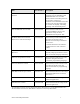
I/O Model Applicable I/O Pins Total Pins per Object Input/Output Value Bit Output1 IO0 – IO11 1 0, 1 binary data Byte Input IO0 – IO7 8 0 – 255 binary data Byte Output IO0 – IO7 8 0 – 255 binary data Leveldetect Input IO0 – IO7 1 Logic 0 level detected Nibble Input Any adjacent four in IO0 – IO7 4 0 – 15 binary data Nibble Output Any adjacent four in IO0 – IO7 4 0 – 15 binary data Touch I/O IO0 – IO7 1 Up to 2048 bits of input or output bits Notes: 1.
Table 31.
Table 32. Summary of the Timer/Counter Input Models Applicable I/O Pins Total Pins per Object Dualslope Input IO0, IO1 + (one of IO4 – IO7) 2 Comparator output of the dualslope converter logic Edgelog Input IO4 1 A stream of input transitions Infrared Input IO4 – IO7 1 Encoded data stream from an infrared demodulator Ontime Input IO4 – IO7 1 Pulse width of 0.2 µs – 1.678 s Period Input IO4 – IO7 1 Signal period of 0.2 µs – 1.
Applicable I/O Pins Total Pins per Object Triac Output2 IO0, IO1 + (one of IO4 – IO7) 2 Delay of output pulse with respect to input edge TriggeredCount Output IO0, IO1 + (one of IO4 – IO7) 2 Output pulse controlled by counting input edges I/O Model Input/Output Value Notes: 1. The Stretched Triac Output model is available for the following device types: FT 5000, Neuron 5000, FT 6000, and Neuron 6000. 2.
addition to the parallel or muxbus object for the following device types: PL 3120E4, PL 3150, or PL 3170. For Series 6000 devices, you can also declare the IO11 pin as a bit input or output in addition to the parallel (master or slave A mode) or muxbus object; the IO11 pin serves as an IRQ pin for the parallel (slave B mode) object. • Direct I/O object types (such as bit, nibble, byte) can be declared in any combination.
I/O Pin 0 1 2 3 4 5 7 8 9 10 11 All Pins 0 – 7 Byte Input, Byte Output DIRECT I/O MODELS 6 Any Pin Bit Input, Bit Output Any Pin 0 – 7 Leveldetect Input Any Four Adjacent Pins Nibble Input, Nibble Output Touch I/O PARALLEL I/O MODELS SERIAL I/O MODELS Muxbus I/O Data Pins 0 – 7 ALS WS Master/Slave A Data Pins 0 – 7 CS R/W HS Slave B Data Pins 0 – 7 CS R/W A0 RS Parallel I/O Bitshift Input, Bitshift Output C D I2C I/O C D C D C D C D C D C D C D IRQ C Magca
Example: The following I/O object types can be combined for a Neuron Chip or Smart Transceiver: • 1 parallel I/O object type (on IO_0..IO10) OR • 1 muxbus I/O object type (on IO_0..IO10) OR • A combination of any or all of the other I/O models A through E shown in Table 34: Table 34.
source and sink capability. If your I/O circuitry has higher current requirements, you can add external driver circuitry (for example, using a Fairchild Semiconductor® 74AC245/74ACT245 Octal Bidirectional Transceiver or 74VHC245/74VHCT245 Octal Buffer/Line Driver). In addition, the Series 6000 device pins are all 3.3 V pins: the input pins are 5 V tolerant, and the output pins are CMOS compatible. Series 3100 device pins are all 5 V pins.
• Events on the I/O pins for the input timer/counter functions are accurately measured, and a value returned to a register, regardless of the state of the application or interrupt processor within the Neuron Chip or Smart Transceiver. However, the application processor can be delayed in reading the register.
7 Programming Considerations This chapter describes software tools for creating applications that run on Series 6000 devices.
Application Program Development You can perform initial development and test for Neuron C applications using the IzoT NodeBuilder Development Tool. You can also perform application debugging using the IzoT NodeBuilder Development Tool. See the IzoT NodeBuilder User’s Guide for detailed instructions on developing, testing, and debugging applications. For initial device development, you should use the FT 6000 EVB Evaluation Boards that are included with the FT 6000 EVK.
the available system clock rates for your device. However, the recommended internal clock speed is 80MHz. The reason is that transient code must be brought in from flash on demand and the time it takes to load such code is directly proportional to the internal clock speed. See the IzoT NodeBuilder User’s Guide for more information. The IzoT NodeBuilder Device Template wizard runs during the creation of a new device template. This wizard provides an opportunity to select predefined hardware templates.
SNMP Support The Series 6000 chip supports SNMP V1. The following are the commands and objects that are implemented. Supported Commands SNMP Get SNMP Get Next Supported Objects Name: system.sysDescr ID: 1.3.6.1.2.1.1.1 A textual description of the entity. This value should include the full name and version identification of the system's hardware type, software operating-system, and networking software. The Neuron's implementation returns the string "Neuron". Name: system.sysObjectID ID: 1.3.6.1.2.1.1.
Name: interfaces.ifOutOctets ID: 1.3.6.1.2.1.2.2.1.16 The total number of octets transmitted out of the interface, including framing characters. Name: interfaces.ifOutUcastPkts ID: 1.3.6.1.2.1.2.2.1.17 The total number of packets that higher-level protocols requested be transmitted, and which were not addressed to a multicast or broadcast address at this sub-layer, including those that were discarded or not sent.
access_nv() access_alias() update_nv() update_alias() Both the NV and Alias configuration structures can be referenced using macros named NV_STRUCT_TYPE and ALIAS_STRUCT_TYPE – these will work regardless of whether the target device supports the extended address table. For the NV_STRUCT_TYPE data type the “nv_addr_index_high” represents the upper 4-bits of an 8-bit address table entry index. The “nv_addr_index” field represents the lower 4 bits.
A Series 6000 Design Checklists This appendix includes a set of checklists, including chip connections, power supplies, PCB layout, and network cabling. These checklists help you ensure that products that you design for the Series 6000 chip meet the specifications described in this manual. You can copy and freely distribute the contents of this appendix.
Checklist 1: Series 6000 Chip Connections This checklist applies to all Series 6000 chips, including FT 6000 Smart Transceivers and Neuron 6000 Processors. Check When Complete Item Description CC1 The VDD3V3 pins (8, 18, 29, 30, 41, and 42) are connected to VDD3 (+3.3 V), as described in Pin Connections. CC2 The VDD1V8 pins (6, 16, and 44) are connected to the VOUT1V8 pin (27) only, as described in Pin Connections. Do not connect an external 1.8 V source to any of the VDD1V8 pins (6, 16, and 44).
Check When Complete Item Description CC10 Capacitors (30 pF 5% 50V NPO) are placed at the XIN and XOUT pins (23 and 24), as described in Clock Requirements. Each capacitor is placed directly adjacent to the XIN and XOUT pins, on the top layer of the PCB, with a short connection to ground. CC11 A feedback resistor (1 MΩ) is added across the XIN and XOUT pins (23 and 24), as described in Clock Requirements.
Checklist 2: FT 6000 Smart Transceiver Connections This checklist applies to FT 6000 Smart Transceivers. Check When Complete 122 Item Description FC1 All items in Checklist 1: Series 6000 Chip Connections. FC2 Environmental and electrical specifications are met, as described in the FT 6000 Free Topology Smart Transceiver data sheet. FC3 The FT-X3 Communications Transformer pins are connected as specified in Transformer Electrical Connections.
Checklist 3: Neuron 6000 Processor Connections This checklist applies to Neuron 6000 Processors. Check When Complete Item Description NC1 All items in Checklist 1: Series 6000 Chip Connections. NC2 Environmental and electrical specifications are met, as described in the Neuron 6000 Processor data sheet. NC3 The connections for the CP0..CP4 pins (32, 34, 37, 38, and 39) match the requirements specified in Connection for a Neuron 6000 Processor.
Checklist 4: Power Supply This checklist applies to all Series 6000 chips, including FT 6000 Smart Transceivers and Neuron 6000 Processors. Check When Complete 124 Item Description PS1 VDD3 = 3.3V ± 0.3V over the full device temperature range and device application current range (including any ripple). PS2 Any ripple on VDD3 is ≤ 50 mVp-p, measured with a 20 MHz bandwidth.
Checklist 5: Device PCB Layout This checklist applies to all Series 6000 chips, including FT 6000 Smart Transceivers and Neuron 6000 Processors. Check When Complete Item Description LO1 Your design incorporates a “star ground” layout design, with the network connector, coupling circuit, power supply input, and externally-accessible I/Os all grouped near each other along one edge (or two adjacent edges) of the PCB.
Checklist 6: Network Cabling and Termination This checklist applies to FT 6000 Smart Transceivers. Check When Complete 126 Item Description NT1 The LONWORKS network uses one of the approved wire types described in Chapter 5, Network Cabling and Connections for FT Devices. NT2 The LONWORKS network uses the appropriate termination, as described in Cable Termination and Shield Grounding.
Checklist 7: Device Programming This checklist applies to all Series 6000 chips, including FT 6000 Smart Transceivers and Neuron 6000 Processors. Check When Complete Item Description PG1 For FT 6000 Smart Transceivers, TP/FT-10 is used as the channel definition in the development tool. For Neuron 6000 Processors, the appropriate channel type is specified. PG2 The device’s hardware template defines the appropriate clock multiplier for the Series 6000 chip’s PLL to specify the system clock rate.
B Qualified TP/FT-10 Cable Specifications This appendix describes generic cable specifications for cables that Echelon has qualified to work with TP/FT-10 channels.
Introduction This appendix documents generic cable specifications for cables that Echelon has qualified to work with TP/FT-10 channels. Specific vendors and their cables are cited only to highlight the variety of cable types available that meet these generic specifications; other vendors may also meet the required specifications. Qualified Cables Echelon has qualified five cable types that are available from a variety of different vendors. Table 35 describes these cables. Table 35.
Notes: • AWG: American wire gauge. See ASTM B258 - 02(2008) Standard Specification for Standard Nominal Diameters and Cross-Sectional Areas of AWG Sizes of Solid Round Wires Used as Electrical Conductors (www.astm.org/Standards/B258.htm) for a definition of the wire gauges. • NEMA: National Electrical Manufacturers Association. www.nema.org • TIA: Telecommunications Industry Association. www.tiaonline.
Table 37. Impedance Characteristics Frequency Impedance (Ohms) 772 kHz 102 ±15% (87-117) 1.0 MHz 100 ±15% (85-115) 4.0 MHz 100 ±15% (85-115) 8.0 MHz 100 ±15% (85-115) 10.0 MHz 100 ±15% (85-115) 16.0 MHz 100 ±15% (85-115) 20.0 MHz 100 ±15% (85-115) Table 38. Attenuation (dB per 1000 feet at 20 °C) Maximums Frequency Attenuation (dB per 1000 feet at 20 °C) 772 kHz 4.5 [for 22 AWG (0.65 mm) cable] 5.7 [for 24 AWG (0.5 mm) cable] 1.0 MHz 5.5 [for 22 AWG (0.65 mm) cable] 6.5 [for 24 AWG (0.
Table 39. Worst-Pair Near-End Crosstalk (dB) Minimums Specification Value (dB) 772 kHz 58 1.0 MHz 56 4.0 MHz 47 8.0 MHz 42 10.0 MHz 41 16.0 MHz 38 20.0 MHz 36 Values in Table 39 are shown for informational use only. The minimum near-end cross talk (NEXT) coupling loss for any pair combination at room temperature is to be greater than the value determined using the following formula for all frequencies in the range of 0.
Table 41. Attenuation and Propagation Delay Characteristics Characteristic Maximum Attenuation 20 ºC 20 kHz 64 kHz 78 kHz 156 kHz 256 kHz 512 kHz 772 kHz 1000 kHz 1.3 dB/km 1.9 dB/km 2.2 dB/km 3.0 dB/km 4.8 dB/km 8.1 dB/km 11.3 dB/km 13.7 dB/km Propagation delay 5.
C FT-X3 Communications Transformer This appendix describes the FT-X3 Communications Transformer, including its pinout, electrical connections, and pad layout.
Transformer Pinout Figure 49 shows the pinout for the FT-X3 Communications Transformer and the equivalent electrical schematic. The FT-X3 Communications Transformer is rotationally symmetric; thus, the package does not mark pin 1. The wiring connections shown in Figure 47 are made on the PCB, as described in Transformer Pad Layout. Table 42 lists the pin assignments for the FT-X3 Communications Transformer.
Transformer Electrical Connections VDD33 VDD33 2 C3 0.1 uF 2 1 VDD33 2 Figure 48 shows the electrical connections for the FT-X3 Communications Transformer. The NETP and NETN signals represent connections to the FT 6000 Smart Transceiver NETP and NETN pins (32 and 34). The NETB and NETA ports represent the connections to the LONWORKS network, as shown in Figure 49.
C6 2 1 NETA 1 22 uF 63V D4B BAV99 3 3 D3B BAV99 + 2 HDR2 200 MIL R/A 1 1 2 D4A BAV99 2 1 D3A BAV99 JP1 2 3 3 VR1 470V C7 NETB + 2 1 22 uF 63V Figure 49. FT Network Electrical Connections In the figure, the diodes D3 and D4 are differential network clamping diodes. Capacitors C6 and C7 are DC blocking capacitors, 22 µF, 63 V, polarized electrolytic aluminum. Varistor VR1 is 470 V, 5 mm.
Notes for the figure: • Maintain a minimum distance of 2 mm between a routed trace and any of the transformer pads or traces. This distance is especially important for the network pins (3, 4, 7, and 8) to maintain EMC compliance. The primary and secondary traces should be kept away from each other as much as possible. • If you use center-tap capacitors, place them near pin 2 (Primary) and pin 8 (Secondary). • Vias and other PCB features are not shown. Use standard practices for vias and trace widths.
D Handling and Manufacturing Guidelines This appendix describes guidelines for handling and manufacturing devices that use the Neuron 6000 Processor or FT 6000 Smart Transceiver, including soldering profiles and ESD handling guidelines.
Application Considerations This section describes application considerations for design and manufacturing of LONWORKS devices. Termination of Unused Pins Because Series 6000 devices are CMOS devices, you must terminate all unused input pins, including undeclared or unconnected I/O pins that are configured as inputs and including three-state pins, to assure proper operation and reliability. Figure 52 shows a CMOS inverter representative of circuitry found on CMOS input pins.
• Connecting individual unused I/O pins directly to GND or to VDD. This method is not recommended in case of software error and because of the possibility of output declaration to an opposing state. • Declaring unused pins as outputs. Thus, you should never connect a pin that is capable of being configured as an output to another such pin or directly to GND or to VDD.
causes leakage or shorts. Often secondary damage occurs after an initial zap failure causes a short. • Latch-up refers to a usually catastrophic condition that is caused by turning on a parasitic, bipolar, silicon-controlled rectifier (SCR). A latch-up is formed by N and P regions in the layout of the integrated circuit, which act as the collector, base, and emitter of parasitic transistors. Bulk resistance of silicon in the wells and substrate acts as resistors in the SCR circuit.
Figure 54. Digital I/O Electrostatic Discharge Design Guidelines There are many ways to deal with ESD, including: • Divert or limit energy from points of contact to circuitry. • Start with a series of electromagnetic interference (EMI) ferrites or resistors for high frequency filtering. • Use diodes, transient voltage suppressors (such as, MOSorbs or transorbs) for highspeed clamping. • Use capacitors to protect critical inputs. • Use good power distribution.
• Use short, low-inductance, traces for the analog circuitry to reduce inductive, capacitive, and radio frequency (RF) noise sensitivities. • Use short, low-inductance, traces for the digital circuitry to reduce inductive, capacitive, and radio frequency (RF) radiated noise. • Connect bypass capacitors between the VDD and GND pairs with minimal trace length.
Hazardous Substances (RoHS) Directive (2002/95/EC), thus their profiles use the lead-free assembly, with a peak temperature Tp of 260 ºC. Soldering Surface Mount (SMT) Parts Table 43 lists the maximum reflow temperature for surface mount (SMT) parts. In all cases, consult the solder manufacturer’s data sheet for recommendations on optimum reflow profile. The actual reflow profile chosen should consider the peak temperature limitations. Table 43.
because they appear as intermittent failures or as degraded performance. Static damage can often increase leakage currents. CMOS devices are not immune to large static voltage discharges that can be generated during handling. For example, static voltages generated by a person walking across a waxed floor have been measured in the 4 kV – 15 kV range (depending on humidity, surface conditions, and so on). Therefore, you should observe the following general precautions: 1.
d. Completed assemblies should be placed in antistatic containers prior to being moved to subsequent stations. Figure 55.
Figure 56. Typical Manufacturing Work Station Notes for Figure 56: 1. 1/16-inch conductive sheet stock covering bench-top work area. 2. Ground strap. 3. Wrist strap in contact with skin. 4. Static neutralizer (ionized air blower directed at work). Primarily for use in areas where direct grounding is impractical. 5. Room humidifier. Primarily for use in areas where the relative humidity is less than 45%.
7. Equipment specifications should alert users to the presence of CMOS devices and require familiarization with this specification prior to performing any kind of maintenance or replacement of devices or modules. 8. Do not insert or remove CMOS devices from test sockets with power applied. Check all power supplies to be used for testing devices to be certain there are no voltage transients present. 9.
• VDD3V3 pins: 8, 18, 29, 30, 31, 41 • VDD1V8 pins: 6, 16, 27, 44 Recommendation: Add an additional 1.0 μF (6.3 V, 10%, X7R) capacitor to pin 27 to provide extra protection and stability for the Series 6000 chip’s internal voltage regulator. Figure 58 shows suggested bypass capacitor placement and crystal circuit trace outlines. See Pin Connections for additional information about placing these capacitors. Figure 58.
Reference Part C12 1.0 µF for pin 27 VOUT1V8 C16 0.01 µF across pins 25 and 26 (VDDPLL and GNDPLL) C17 0.1 µF for pin 16 VDD1V8 C18 0.1 µF for pin 18 VDD3V3 C23 30 pF for pin 23 XIN C24 30 pF for pin 24 XOUT R19 200 Ω for pin 24 XOUT R61 1 MΩ across pins 23 and 24 (XIN and XOUT) Y1 External 10 MHz crystal Key Layout Rules: 1. If possible, use 4-layer boards (or boards with more than four layers). Additional layers simplify the layout, and reduce noise-related and grounding problems. 2.
E Example Schematic This appendix provides an example schematic for an FT 6000 Smart Transceiver, with associated non-volatile memory, communications transformer, and network connections.
Example Schematic This appendix provides an example schematic for an FT 6000 Smart Transceiver. The example schematics are based on the FT 6000 Evaluation Board that is included with the FT 6000 Evaluation Kit.
Memory Interface Connections Figure 61 shows the connections for the serial memory interface. The figure shows connections to a a flash memory device. The 49.9 Ohm series resistors are not generally needed, and can be omitted. The 100k Ohm pulldown on MISO can also be omitted. Figure 61. Memory Interface Connections Transformer Connections Figure 62 shows the connections for the communications transformer.
C101 22uF 63V ALUM ELEC 1 2 NETB VDD5 3 SVC- D101A BAV99 75V FT Network FT_NETB 1 3 1 2 D101B BAV99 75V 3 2 + D213 BAV99 75V JP101 FT_NETA 2 XR8 1 1 HDR2 200MIL R/A VDD5 2 1 D102A BAV99 75V D214 BAV99 75V NETA 1 2 2 HDR2 200MIL R/A 2 3 3 JP102 RV1 470V D102B BAV99 75V 2 1 + C102 22uF 63V ALUM ELEC FT 5000_CORE NETB NETB NETA NETA CP4 CP4 CP3_RX CP3_RXLED CP2_TX CP2_TXLED CP1 CP1 SVCRST- SVCRST- CP0 CP0 2 LED202 LED GREEN "RX" 1 IO0 IO1 IO2 IO3 IO4 IO5 IO6
Reference Designator Value C6 1.0 µF C101, C102 22 µF D1, D2, D3, D4, D101, D102, D213, D214, D215, D216 BAV99 L1, L2 150 Ω R6, R7, R8, R13 49.9 Ω R18, R202, R203 200 Ω R206 499 Ω R205 1.00 kΩ R1, R9, R10, R12 4.99 kΩ R2, R3, R4, R5 100 kΩ R15 1 MΩ RV1 470 V T2 Echelon FT-X3 T1 Echelon FT-X2 (not needed if FT-X3 is present) U1 Echelon FT 6000 Smart Transceiver U3 Winbond W25Q80BV serial flash Y1 10.
F Vendor Contact Information This appendix lists contact information for many of the product vendors mentioned in this manual.
Vendor Information This appendix lists contact information for many of the product vendors mentioned in this manual. For most of the parts listed in this manual, Echelon does not require that you use these vendors, but recommends products from the vendors listed. Abracon Corporation Headquarters 30332 Esperanza Rancho Santa Margarita, CA 92688 USA Phone: +1 949-546-8000 Fax: +1 949-546-8001 www.abracon.
BPM Microsystems Headquarters 5373 West Sam Houston Pkwy N, Suite 250 Houston, TX 77041 USA Phone: +1 713-688-4600 Toll Free (US): 800-225-2102 Fax: +1 713-688-0920 www.bpmmicro.com Citel Inc. Headquarters 11381 Interchange Circle South Miramar, FL 33025 USA Phone: +1 954-430-6310 Toll Free (US): 800-248-3548 Fax: +1 954-430-7785 www.citelprotection.com CommScope Inc. Headquarters 1100 CommScope Place SE Hickory, NC 28603 USA Phone: +1 828-324-2200 Toll Free (US): 800-982-1708 www.commscope.
Emulation Technology Inc. Headquarters 2320 Walsh Avenue Building H, Suite E Santa Clara, CA 95051 USA Toll Free (US): 800-ADAPTER (800-232-7837) www.emulation.com Fairchild Semiconductor Inc. Headquarters Corporate Offices 82 Running Hill Road South Portland, ME 04106 USA Phone: +1 207-775-8100 Toll Free (US): 800-341-0392 3001 Orchard Parkway San Jose California 95134 USA Phone: +1 408-822-2000 www.fairchildsemi.com HiLo System Research Company Ltd. Headquarters 4F, No. 18, Lane 76 Rueiguang Rd.
Laird Technologies PLC Headquarters US Office 100 Pall Mall London UK SW1Y 5NQ 16401 Swingley Ridge Road Suite 700 Chesterfield, MO 63017 USA Phone: +1 636-898-6000 Fax: +1 636-898-6100 Phone: +44 (0)20 7468 4040 Fax: +44 (0)20 7839 2921 www.lairdtech.com Littelfuse Inc. Headquarters 8755 West Higgins Road Suite 500 Chicago IL 60631 USA Phone: +1 773-628-1000 Fax: +1 847-391-0894 www.littelfuse.com Numonyx BV Headquarters Americas Regional Sales Office A-One Biz Center Z.A.
NXP Semiconductors BV Headquarters High Tech Campus 45 5656 AE Eindhoven Netherlands Phone: +31 40 27 29999 Fax: +31 40 27 43375 www.nxp.com ON Semiconductor Headquarters 5005 East McDowell Road Phoenix, AZ 85008 USA Phone: +1 602-244-6600 Toll Free (US): 888-743-7826 www.onsemi.com Panasonic Corp.
Plastronics Socket Company Inc. Headquarters 2601 Texas Drive Irving, Texas 75062 USA Phone: +1 972-258-2580 Toll Free (US): 800-582-5822 Fax: +1 972-258-6771 www.plastronicsusa.com Sankosha Corp. Headquarters US Office 4-3-8 Osaki Shinagawa-ku, Tokyo 141 Japan Phone: 81-3-3491-7181 Fax: 81-3-3494-7574 406 Amapola Avenue, Suite 135 Torrance, CA 90501 USA Phone: +1 310-320-1661 Toll Free (US): 888-711-2436 Fax: +1 310-618-6869 www.sankosha-usa.com Silicon Storage Technology Inc.
Taiyo Yuden Company Ltd. Headquarters US Office Matsumura Bldg. 6-16-20 Ueno Taito-Ku, Tokyo 110-0005 Japan Phone: 81-3-3833-5441 Fax: 81-3-3835-4754 1930 North Thoreau Drive, Suite 190 Schaumburg, IL 60173 USA Phone: +1 847-925-0888 Fax: +1 847-925-0899 www.t-yuden.com or www.yuden.co.jp/e/index.html TDK Corp. Headquarters US Office 1-13-1, Nihonbashi, Chuo-ku Tokyo, 103-8272 Japan 901 Franklin Avenue P O Box 9302 Garden City, NY 11530-9302 USA Phone: +1 516-535-2600 Fax: +1 516-294-8318 www.tdk.
Vishay Intertechnology Inc. Headquarters 63 Lancaster Avenue Malvern, PA 19355-2143 USA Phone: +1 402-563-6866 Fax: +1 402-563-6296 www.vishay.