ch4540 (73454) - pto Manual PN 12127 Rev.
Before You Begin DEAR ECHO BEAR CAT CUSTOMER Thank you for purchasing a ECHO Bear Cat product. The ECHO Bear Cat line is designed, tested, and manufactured to give years of dependable performance. To keep your machine operating at peak efficiency, it is necessary to adjust it correctly and make regular inspections. The following pages will assist you in the operation and maintenance of your machine. Please read and understand this manual before operating your machine.
LIMITED WARRANTY This warranty applies to all AG and Outdoor Power Equipment manufactured by Crary Industries. The warranty registration must be completed and returned to Crary Industries within 10 days of delivery of the product to the original owner or the warranty will be void. In the event of a failure, return the product, at your cost, along with proof of purchase to the selling Crary Industries dealer.
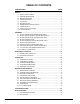
TABLE OF CONTENTS DESCRIPTION PAGE SAFETY................................................................................................................. 1 1.1 SAFETY ALERT SYMBOL.....................................................................................1 1.2 EMISSION INFORMATION....................................................................................1 1.3 before operating...........................................................................................1 1.
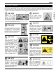
1 Section SAFETY 1.1 SAFETY ALERT SYMBOL Failure of the owner/operator of the equipment to comply with this regulation is a misdemeanor under California law and may also be a violation of other state and/or federal regulations, laws, ordinances, or codes. Contact your local fire marshal or forest service for specific information about which regulations apply in your area. The Owner/Operator’s manual uses this symbol to alert you of potential hazards.
SAFETY or ill. You must be in good health to operate this machine safely. 7. Do not operate this equipment in the vicinity of bystanders. Keep the area of operation clear of all persons, particularly small children. It is recommended that bystanders keep at least 50 feet (15 meters) away from the area of operation. 8. Do not allow children to operate this equipment. 9. Use only in daylight or good artificial light. 10. Do not run this equipment in an enclosed area.
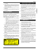
SAFETY 8. Proper recommended PTO operating speed is 540 +/- 10 RPM. 9. Before inspecting or servicing the PTO drive area, disengage the driveline, shut off power source, remove ignition key, and make sure all moving parts have come to a complete stop. 11. Do not clean, lubricate or adjust the PTO shaft when it is running. 1.6 battery safety Improper use and care of the battery on electric start models can result in serious personal injury or property damage.
SAFETY 1.9 safety decal locations The numbers below correspond to the decals in Section 1.10. Familiarize yourself with all of the safety and operational decals on the machine and the associated hazards. See the engine owner’s manual or contact the engine manufacturer for engine safety instructions and decals. Make certain that all safety and operating decals on this machine are kept clean and in good condition. Decals that need replacement must be applied to their original locations.
SAFETY 1.10 safety decals See Section 1.9 for decal locations. Familiarize yourself with all of the safety and operating decals on the machine and the associated hazards. See the engine owner’s manual or contact the engine manufacturer for engine safety instructions and decals. Make certain that all safety and operational decals on this machine are kept clean and in good condition. Decals that need replacement must be applied to their original locations.
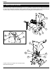
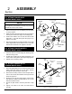
2 Section ASSEMBLY 2.1 attach trailer axle (engine model only) 1/2” x 1-1/4” BOLT FENDER note Axle, wheel and hitch assemblies for some models are supplied by the distributor and may vary from the illustrations shown in this manual. 1. Remove the chipper from the shipping crate and place on a level surface. 3/8” x 1-1/4” BOLT AXLE MOUNTING BRACKET 3/8” NUT 2. Raise the trailer several inches from the ground with a hoist or jack. Ensure the chipper is well supported. 3.
ASSEMBLY 2.6 attach discharge tube 2.4 attach chipper chute 1. Use a support or hoist to hold the chipper chute in place on the chipper frame. 1. Slide the blower tube discharge clamp underneath the mounting flange on the chipper frame. 2.5 attach extension tray (Euro model only) WARNING Do not operate this unit without the chipper chute correctly installed. Rotating cutting blades can cause serious personal injury. 3/8” x 1-1/4” BOLT BLOWER DISCHARGE TUBE SPACER 1.
ASSEMBLY 2.7 install battery (engine model only) 2.8 check/add motor oil (engine model only) You will need to purchase a battery. Choose a battery that meets or exceeds the following specifications: Nominal Voltage: 12 Volt CCA@ Zero Degree: 250 Size: 7-1/8" x 3" x 6-9/16" Rated Capacity:18 AH Check the oil level. If needed, fill the engine with the type and amount of oil specified in the engine owner's manual. 2.
ASSEMBLY 6. File both shaft ends, and slide the two halves back together. 2.10 connect pto driveline 2.10.3 connecting the pto driveline IMPORTANT The tractor must have a standard 540 RPM PTO shaft. • If the tractor has an electric PTO clutch, consult your dealer for correct operating procedures. 2. Connect the opposite end of the PTO shaft to the tractor. 2.10.1 CHECK LENGTH OF PTO DRIVELINE 1. Attach chipper to tractor with three-point hitch. 2.
3 Section FEATURES & CONTROLS 3.1 engine model controls 3.1.1 chipper controls 1. Trailer hitch: Always use 2 inch (50 mm) ball and safety chains. 2. Jack stand: Always have in UP position and clear from ground when moving. When in use, place in DOWN position on a level surface. 4 5 3. Belt guard: Never remove guards when in use. 4. Discharge tube: Chipped materials exit through the rotatable discharge chute. 5. Chipper chute: Feed materials to be chipped through the chipper chute. 6.
FEATURES AND CONTROLS 3.2 pto model controls 4. Chipper chute: Feed materials to be chipped through the chipper chute. 2. PTO driveline: Connects chipper to tractor PTO shaft. Avoid driveline angles over 20 degrees on PTO when unit is in use. NOTE: Minimum and maximum telescoping on the PTO driveline are 18.11" and 24.49". This will leave a 6.43" overlap. See Section 2.10 for instructions on checking driveline length. 5.
4 OPERATION Section 4.2 stopping PTO model As with any other piece of outdoor equipment, getting the feel for how your machine operates and getting to know the best techniques for particular jobs are important to overall good performance. 1. Move tractor throttle to slowest position. CHIPPING OPERATION 3. Allow machine to come to a complete stop. The chipping operation takes place on the front of the machine, where hardened steel chipper blades are mounted on a rotating disk assembly.
OPERATION note The heavy rotor will continue to turn for some time after the engine or tractor has been shut off. You can tell that the rotor has stopped when no noise or machine vibration is present. Inserting a branch into the chipper chute to contact the blades will slow the rotor and shorten stopping time. WARNING Read and follow all safety instructions in this manual.
5 Section SERVICE & MAINTENANCE 5.1 maintenance schedule The items listed in this service and maintenance schedule are to be checked, and if necessary, corrective action taken. This schedule is designed for units operating under normal conditions. If the unit is operating in adverse or severe conditions, it may be necessary for the items to be checked and serviced more frequently.
SERVICE & MAINTENANCE WARNING BEFORE INSPECTING OR SERVICING ANY PART OF THIS MACHINE, SHUT OFF POWER SOURCE AND MAKE SURE ALL MOVING PARTS HAVE COME TO A COMPLETE STOP. 5.3 removing the blades 5.2 CHIPPER BLADE maintenance To remove the chipper blades: WARNING The chipper blades will eventually become dull, making chipping difficult and adding extra strain on the machine. Check the sharpness of the blades every 5 - 15 hours of operation and sharpen as needed.
SERVICE & MAINTENANCE WARNING BEFORE INSPECTING OR SERVICING ANY PART OF THIS MACHINE, SHUT OFF POWER SOURCE AND MAKE SURE ALL MOVING PARTS HAVE COME TO A COMPLETE STOP. 5. Remove an equal amount off each blade to maintain rotor balance. 5.6.1 engine model drive belt 6. Small imperfections such as nicks and burrs on the flat side of the blade will not affect the chipping performance of the machine. 2. Remove belt guard. 7.
WARNING SERVICE & MAINTENANCE BEFORE INSPECTING OR SERVICING ANY PART OF THIS MACHINE, SHUT OFF POWER SOURCE AND MAKE SURE ALL MOVING PARTS HAVE COME TO A COMPLETE STOP. of pulleys and belt tension. Adjust if needed. 4. Install the new belts and reinstall idler pulley. 5. Check pulley alignment with a straight edge and adjust if needed. 7. Reinstall belt guard. 8. Start tractor engine and engage PTO drive clutch (see tractor owner's manual). Increase engine speed to rated PTO RPM.
SERVICE & MAINTENANCE WARNING BEFORE INSPECTING OR SERVICING ANY PART OF THIS MACHINE, SHUT OFF POWER SOURCE AND MAKE SURE ALL MOVING PARTS HAVE COME TO A COMPLETE STOP. 5.9 lubrication Lubricate the machine periodically with a lithium-based grease. Extreme working conditions will require more frequent greasing. IMPORTANT Polyurea and lithium-based greases are not compatible. Mixing the two grease types may lead to premature failure.
6 Section TROUBLESHOOTING PROBLEM Engine will not start. POSSIBLE CAUSES REMEDY Improper control settings. Use proper settings. Lack of fuel. Fill fuel tank. Spark plug disconnected. Connect spark plug. Dirty, stale or contaminated gas. Refill gas tank with fresh, clean unleaded regular gasoline. Internal engine problems. See your dealer. Obstructed discharge. Use branch or similar object to clear discharge. Engine or rotor stalls or Plugged rotor. stops.
TROUBLESHOOTING Rotor will not turn. Cannot engage clutch. Excessive belt wear. Trailer sways during towing. 7 Drive belt too loose or broken. Replace belt or spring. Obstructed discharge. Use branch or similar object to clear discharge. Plugged rotor. Clear rotor. Feed material more evenly. Improper belt installation; belt not under belt guide. Install belt properly; install belt under belt guide. Improper belt tension. Adjust belt tension. Replace belt or spring if needed.
7.2 bolt torque The tables below are for reference purposes only and their use by anyone is entirely voluntary, unless otherwise noted. Reliance on their content for any purpose is at the sole risk of that person and any loss or damage resulting from the use of this information is the responsibility of that person. SAE - 2 SAE - 5 BOLT DIAMETER SAE - 8 A ENGLISH BOLT TORQUE * BOLTDIAMETER(A) SAE 2 SAE 5 N.m Ft-lb. N.m Ft-lb. N.m Ft-lb. 1/4” 7.5 5.
22 4 INCH CHIPPER
ENGLISH 4 INCH CHIPPER 23
ECHO BEAR CAT www.bearcatproducts.com 237 NW 12th Street, West Fargo, ND 58078-0849 Phone: 701.282.5520 • Toll Free: 800.247.7335 • Fax: 701.282.9522 E-mail: service@bearcatproducts.com • sales@bearcatproducts.