POWER EDGER ATTACHMENT OPERATOR'S MANUAL Power Edger Attachment Operator's Manual MODEL 99944200470 - S06000057000 Serial Number S06000001001 001001 - 057000 MODELS USED ON: SRM-2100SB/2400SB SRM-210SB/211SB SRM-260SB/261SB PAS 2100/2400 PAS 210/211 PAS 230/231 PAS 260/261 WARNING DANGER Read rules for safe operation and instructions carefully. ECHO provides an Operator's Manual and a Safety Manual Pro Attachment Series power source or Split Boom Trimmer.
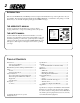
INTRODUCTION Welcome to the ECHO family. This ECHO product was designed and manufactured to provide long life and on-the-jobdependability. Read and understand this manual and the SAFETY MANUAL you found in the same package. You will find both easy to use and full of helpful operating tips and SAFETY messages. THE OPERATOR'S MANUAL Contains specifications and information for operation, starting, stopping, maintenance, storage and assembly specific to this product.
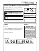
POWER EDGER ATTACHMENT OPERATOR'S MANUAL MANUAL SAFETY SYMBOLS AND IMPORTANT INFORMATION Throughout this manual and on the product itself, you will find safety alerts and helpful, information messages preceded by symbols or key words. The following is an explanation of those symbols and key words and what they mean to you. This symbol accompanied by the words WARNING and DANGER calls attention to an act or condition that can lead to serious personal injury to operator and bystanders.
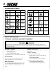
INTERNATIONAL SYMBOLS Symbol form/shape Symbol Symbol form/shape description/application Symbol description/ application Read and understand Operator's Manual. Fuel and oil mixture Wear eyes, ears and head protection Finger Severing Symbol form/shape Wear hand protection. Use two handed. Hot Surface Symbol description/application Symbol form/shape Symbol description/ application Keep feet away from blade Direction of blade Thrown objects Emergency stop Wear slip resistant foot wear.
POWER EDGER ATTACHMENT OPERATOR'S MANUAL EXTENDED OPERATION/EXTREME CONDITIONS Vibration and Cold -It is believed that a condition called Raynaud’s Phenomenon, which affects the fingers of certain individuals may be brought about by exposure to vibration and cold. Exposure to vibration and cold may cause tingling and burning sensations followed by loss of color and numbness in the fingers.
SAFE OPERATION Provide Safety And Operating Instructions To All Operators • Provide all users of this equipment with the Operator's Manual and Safety Manual for instructions on Safe Operation. Keep A Firm Grip • Hold the front and rear handles with both hands with thumbs and fingers encircling the handles Keep A Solid Stance • Maintain footing and balance at all times. Do not stand on slippery, uneven or unstable surfaces. Do not work in odd positions or on ladders. Do not over reach.
POWER EDGER ATTACHMENT OPERATOR'S MANUAL 7 SPECIFICATIONS MODEL ----------------------------------------------------- POWEREDGERATTACHMENT Shaft Length ------------------------------------------------ 845 mm (33.25in.) Attachment Width ----------------------------------------- 165.1 mm (6.50 in.) Attachment Height ---------------------------------------- 552.45 mm (21.75 in.) Weight w/blade -------------------------------------------- 2.3 kg (4.96 lb.
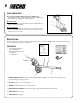
4. Rotate locator pin (A) 1/4 turn clockwise to engage lower shaft hole. Insure locator pin is fully engaged by twisting lower drive shaft. Locator pin should snap flush in coupler. Full engagement will prevent further shaft rotation. D C 5. Secure lower shaft assembly to coupler by tightening clamping knob (D). E OPERATION NOTE Refer to your Pro Attachment Series Operator's Manual for correct engine fueling, starting and stopping instructions. Operating Techniques 1.
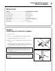
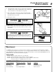
POWER EDGER ATTACHMENT OPERATOR'S MANUAL 4. Adjust the blade's depth of cut to produce a fine cut between sidewalk and grass using a minimum blade depth, usually with about 13 mm (1/2 in.) of the blade into the ground. WHEEL ADJUSTMENT KNOB INCREASE DEPTH 5. Before edging, plan your direction of travel so that the unit will always be positioned on your right side and so that you walk on a hard surface whenever possible. DECREASE DEPTH 6. Hold edger as shown. WARNING 1/2 in.
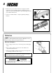
BLADE REPLACEMENT/LUBRICATION Level 1. Tools Required: Scrench, Locking Tool, Needle Nose Pliers, 8 mm Open End Wrench, Grease Gun Parts Required: ECHO® LUBETM 8 oz. (P/N 91014) or Lithium Base Grease, Blade P/N 69601552632 Gear Case NOTE Grease gear case every 50 hours of use. Replace blade when it is worn shorter than 6 in. Remove blade and holders before greasing to prevent damage to gear and bearings. 1. Shut engine off. 2. Remove split pin (A). 3.
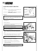
POWER EDGER ATTACHMENT OPERATOR'S MANUAL Drive Shaft (Lower) IMPORTANT Lower and upper drive shaft must be lubricated with high temperature automotive grease every 25 hours of operation, otherwise drive shaft assembly overheating and failure can result. B A 1. Loosen two (2) screws (A) and remove center locating screw (B). Pull gear box and shield from drive shaft housing. 2. Pull flexible cable (C) from the drive shaft housing, wipe clean and re-coat with a thin coating [15 ml (1/2 oz.
SERVICING INFORMATION PARTS Genuine ECHO Parts and ECHO REPOWER™ Parts and Assemblies for your ECHO products are available only from an Authorized ECHO Dealer. When you do need to buy parts always have the Model Number and Serial Number of the attachment with you. You can find these numbers on the driveshaft model/serial number label. For future reference, write them in the space provided below. Model No. ____________ SN. __________ DEALER? Call 1-800-432-ECHO www.echo-usa.
SUPPLEMENT TO OPERATOR'S MANUAL PART NUMBER X7532278700 (X753001210) FOR MODEL: POWER EDGER ATTACHMENT P/N 99944200470 S/N 001001 & UP This Supplement contains important information. Please keep with your Operator's Manual. Your unit was manufactured using Echo’s new open-face, all-metal blade guard, and improved heavy-duty gear case. Specification (Pg. 7) Gear Ratio ----------------------------- 2.07:1 Weight w/Blade ---------------------- 2.54 kg (5.6 lbs.