FOR MODELS: SRM-2100SB, 2400SB, 210SB, 211SB, 225SB, 260SB, 261SB, PAS-2100, 2400, 2601, 210, 211, 225, 225VP, 225VPB, 230, 231, 260, 261, 265, 266, 280 Operator’s Manual Read and understand operator’s manual (and safety manual if included) before use. Failure to read the manuals could result in serious injury. Specifications, descriptions and illustrative material in this literature are as accurate as known at the time of publication, but are subject to change without notice.
TABLE OF CONTENTS 99944200545 TABLE OF CONTENTS Table of Contents ........................................................................................ 2 Introduction ................................................................................................. 3 Servicing Information .................................................................................. 3 Parts/Serial Number ............................................................................ 3 Service...........................
99944200545 INTRODUCTION INTRODUCTION For questions regarding terms used in this manual, visit: https://www.echo-usa.com/Support-Help/TechnicalDocuments OR https://www.shindaiwa-usa.com/Tech-Support/TechnicalDocuments SERVICING INFORMATION Parts/Serial Number Genuine ECHO Parts and Assemblies for your ECHO products are available only from an Authorized ECHO Dealer. When you do need to buy parts always have the Model Number and Serial Number of the unit with you.
SAFETY 99944200545 ECHO Consumer Product Support If you require assistance or have questions concerning the application, operation, or maintenance of this product, call the ECHO Consumer Product Support Department at 1-800-673-1558 from 8:00 am to 5:00 pm (Central Standard Time) Monday through Friday. Before calling, please know the model and serial number of your unit. Product Registration Register your ECHO equipment on-line at www.echo-usa.
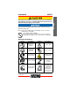
99944200545 SAFETY The enclosed message provides information necessary for the protection of the unit. Note: This enclosed message provides tips for use, care and maintenance of the unit. CIRCLE AND SLASH SYMBOL This symbol means the specific action shown is prohibited. Ignoring these prohibitions can result in serious or fatal injury. International Symbols Symbol X7702093807 © 3/2018 ECHO Inc.
SAFETY Symbol 99944200545 Description Symbol DO NOT USE BLADES - Line Head Only Plan retreat path from falling objects. Description Thrown Objects p Hot Surface AVOID KICKOUT Keep Bystanders At Least 15 m (50 ft.) Away Beware Thrown Objects Wear Eye Protection Keep Bystanders and Helpers Away 15 m (50 ft.) Personal Condition and Safety Equipment Cancer and Reproductive Harm www.P65Warnings.ca.gov The muffler or catalytic muffler and surrounding cover may become extremely hot.
99944200545 SAFETY Physical Condition Your judgment and physical dexterity may not be good: • If you are tired or sick ENGLISH • If you are taking medication • If you have taken alcohol or drugs Operate unit only if you are physically and mentally well. Eye Protection ◆ ◆ Eye protection that meets ANSI Z87.1 or CE requirements must be worn whenever you operate the unit.
SAFETY 99944200545 • DO NOT WEAR TIES, SCARVES, JEWELRY, or clothing with loose or hanging items that could become entangled in moving parts or surrounding growth. • Keep clothing buttoned or zipped, and keep shirt tails tucked in. Wear sturdy work shoes with nonskid rubber soles: • DO NOT WEAR OPEN TOED SHOES. • DO NOT OPERATE UNIT BAREFOOTED. Keep long hair away from engine and air intake. Retain hair with cap or net.
9944200545 SAFETY • Keep your body warm, especially the head, neck, feet, ankles, hands, and wrists. ENGLISH • Maintain good blood circulation by performing vigorous arm exercises during frequent work breaks, and also by not smoking. • Limit the hours of operation. Try to fill each day with jobs where operating the unit or other handheld power equipment is not required.
SAFETY 99944200545 • Immediately stop using all power equipment and consult a doctor if you feel tingling, numbness, or pain in the fingers, hands, wrists, or arms. The sooner RSI/CTS is diagnosed, the more likely permanent nerve and muscle damage can be prevented. All over head electrical conductors and communications wires can have electricity flow with high voltages. This unit is not insulated against electrical current.
99944200545 SAFETY Equipment Moving parts can amputate fingers or cause severe injuries. Keep hands, clothing and loose objects away from all openings. ◆ ALWAYS stop engine, disconnect spark plug, and make sure all moving parts have come to a complete stop before removing obstructions, clearing debris, or servicing unit. ◆ DO NOT start or operate unit unless all guards and protective covers are properly assembled to unit. ◆ NEVER reach into any opening while the engine is running.
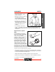
DESCRIPTION 99944200545 DESCRIPTION Locate the safety decal(s) on your unit. Make sure the decal(s) is legible and that you understand and follow the instructions on it. If a decal cannot be read, a new one can be ordered from your ECHO dealer. 1 4 2 3 Shaft Label 1. DRIVE SHAFT ASSEMBLY - Contains a specially designed liner and the flexible drive shaft. 2.
99944200545 CONTENTS CONTENTS The ECHO product you purchased has been factory pre-assembled for your convenience. Due to packaging restrictions, some assembly may be necessary. ____ 1 - PAS Trimmer Attachment ____ 1 - Operator's Manual ____ 1 - Warranty Sheet ____ 1 - Storage Hook Assembly ASSEMBLY Power Head Shaft to Lower Shaft Assembly Do not perform maintenance or assembly procedures with engine running. Parts Required: PAS or SRM-SB Power Head Shaft and Coupling 1.
OPERATION 99944200545 Note: Earlier model power heads may have shorter couplings. Note: Lower bearing housing and head assembly must be in line with the engine. 6. 7. Rotate locater pin (A) ¼ turn clockwise to engage lower shaft hole. Insure locater pin is fully engaged by twisting lower drive shaft. Locater pin should snap flush in coupler. Full engagement will prevent further shaft rotation. D A Secure lower shaft assembly to coupler by tightening clamping knob (D).
99944200545 MAINTENANCE MAINTENANCE Operating a poorly maintained unit can result in serious injuries to operator or bystanders. Always follow all maintenance instructions as written, otherwise serious personal injury may result. Your unit is designed to provide many hours of trouble free service. Regular scheduled maintenance will help your unit achieve that goal. If you are unsure or are not equipped with the necessary tools, we recommend that you take your unit to a Servicing Dealer for maintenance.
MAINTENANCE 99944200545 Maintenance Intervals Component/ System Drive Shaft Gear Housing Screws/Nuts/Bolts Maintenance Procedure Skill Level Interval Every 25 hours of use1 Grease 1 Inspect/Tighten/ Replace Every 50 hours of use1 Before Each Use IMPORTANT - Time intervals shown are maximum. Actual use and your experience will determine the frequency of required maintenance. 1. Apply lithium based grease. Lubrication Level 1. Parts Required: Lithium Based Grease. Gear Housing 1.
99944200545 MAINTENANCE Drive Shaft (Lower) 1. Loosen screw (B) and remove locating screw (C). Pull gear case and shield from drive shaft housing. Pull flexible cable from the drive shaft housing, wipe clean and re-coat with 15 ml (0.5 oz.) of grease. 3. Slide the flexible cable back in the drive housing. DO NOT get dirt on the flex cable. 4. Install the gear housing and shield assembly. ENGLISH 2. B C Nylon Line Replacement Wear Gloves or personal injury may result: ◆ Cutoff knife is sharp.
MAINTENANCE 3. Hold the spool, opening toward you. Place index finger between the two strands and wind line, tightly and evenly, in direction of arrow (E). 4. Place ends of line into notches (F) in spool, leaving 6 in. protruding. 5. 6. Feed ends of line outward through eyelets (G) in drum. E F I G Align grooves in spool with pegs (I), and push spool (B), into drum. 7. Hold spool and drum securely with one hand, and pull each line to disengage from notches. 8.
99944200545 STORAGE STORAGE Storage Hook Installation Insert small end of hook into locating hole on attachment shaft. 2. Slide plastic cap onto end of attachment shaft. ENGLISH 1. SPECIFICATIONS MODEL Shaft Length Attachment Width Attachment Height Weight (dry) w/line head Drive Shaft Direction of Rotation Gear Case Ratio Cutter Head Line Capacity X7702093807 © 3/2018 ECHO Inc. 99944200545 838 mm (32.99 in.) 177 mm (6.97 in.) 241 mm (9.49 in.) 1.18 kg (2.6 lb.) 6.
PRODUCT REGISTRATION 99944200545 PRODUCT REGISTRATION Thank you for choosing ECHO Power Equipment Please go to http://www.echo-usa.com/Warranty/Register-Your-ECHO to register your new product on-line. It's FAST and EASY! NOTE: your information will never be sold or misused by ECHO, Inc. Registering your purchase enables us to contact you in the unlikely event of a service update or product recall, and verifies your ownership for warranty consideration.
99944200545 PRODUCT REGISTRATION ENGLISH X7702093807 © 3/2018 ECHO Inc.
NOTES 99944200545 NOTES 22 X7702093807 © 3/2018 ECHO Inc.
99944200545 NOTES ENGLISH X7702093807 © 3/2018 ECHO Inc.
S08900027801/S08900999999 ECHO, INCORPORATED 400 Oakwood Road Lake Zurich, IL 60047 www.echo-usa.