
Full Product Manual


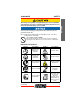
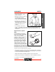
Table Of Contents
- 99944200545 Pro-TorqueTM Trimmer Attachment
- Table of Contents
- Table of Contents 2
- Introduction 3
- Description 12
- Product Registration 20
- Notes 22
- Introduction
- Description
- 1. DRIVE SHAFT ASSEMBLY - Contains a specially designed liner and the flexible drive shaft.
- 2. NYLON CUTTING ATTACHMENT - Contains replaceable nylon trimming line that advances when the trimmer head is tapped against the ground while the head is turning at normal operating speed.
- 3. CUT-OFF KNIFE - Automatically trims line to the correct length after head is tapped on the ground. If trimmer is operated without a cut-off knife the line will become too long, the engine will overheat, and engine damage may occur.
- 4. DEBRIS SHIELD with CUT-OFF KNIFE - Required when unit is equipped with nylon line head. Do not operate unit without shield.
- Contents
- Assembly
- Power Head Shaft to Lower Shaft Assembly
- 1. Set Power Head/Shaft Assembly on a level surface.
- 2. Pull locater pin (A) out, and turn counter-clockwise ¼ turn to lock-out position.
- 3. Remove vinyl cap from attachment drive shaft.
- 4. Remove cardboard spacer, if necessary.
- 5. Carefully fit attachment drive shaft assembly into coupler (B) to decal assembly line (C), making sure that the inner lower drive shaft engages the square upper drive shaft socket.
- 6. Rotate locater pin (A) ¼ turn clockwise to engage lower shaft hole. Insure locater pin is fully engaged by twisting lower drive shaft. Locater pin should snap flush in coupler. Full engagement will prevent further shaft rotation.
- 7. Secure lower shaft assembly to coupler by tightening clamping knob (D).
- Power Head Shaft to Lower Shaft Assembly
- Operation
- Maintenance
- Skill Levels
- Maintenance Intervals
- Lubrication
- Gear Housing
- Drive Shaft (Lower)
- 1. Loosen screw (B) and remove locating screw (C). Pull gear case and shield from drive shaft housing.
- 2. Pull flexible cable from the drive shaft housing, wipe clean and re-coat with 15 ml (0.5 oz.) of grease.
- 3. Slide the flexible cable back in the drive housing. DO NOT get dirt on the flex cable.
- 4. Install the gear housing and shield assembly.
- Nylon Line Replacement
- 1. Do not push spool in. Hold drum (A) and turn spool (B) clockwise until peg clicks and disappears from hole. Pull spool out of drum.
- 2. Use one piece of new nylon line (C) 6 m (20 ft.) long and thread through the molded loop (D) on the spool. Pull line tight and adjust so one end is 15 cm (6 in.) longer than the other.
- 3. Hold the spool, opening toward you. Place index finger between the two strands and wind line, tightly and evenly, in direction of arrow (E).
- 4. Place ends of line into notches (F) in spool, leaving 6 in. protruding.
- 5. Feed ends of line outward through eyelets (G) in drum.
- 6. Align grooves in spool with pegs (I), and push spool (B), into drum.
- 7. Hold spool and drum securely with one hand, and pull each line to disengage from notches.
- 8. Hold drum (A) and turn spool (B) counterclockwise until peg clicks into hole.
- 9. Trim lines to 8 in. length.
- Storage
- Specifications
- Product Registration
- Notes

SAFETY 99944200545
8 X7702093807
© 3/2018 ECHO Inc.
• DO NOT WEAR TIES, SCARVES, JEWELRY, or clothing with loose or
hanging items that could become entangled in moving parts or
surrounding growth.
• Keep clothing buttoned or zipped, and keep shirt tails tucked in.
Wear sturdy work shoes with nonskid rubber soles:
• DO NOT WEAR OPEN TOED SHOES.
• DO NOT OPERATE UNIT BAREFOOTED.
Keep long hair away from engine and air intake. Retain hair with cap or net.
Heavy protective clothing can increase operator fatigue, which may lead to
heat stroke. Schedule heavy work for early morning or late afternoon hours
when temperatures are cooler.
The components of this machine generate an electromagnetic
field during operation, which may interfere with some
pacemakers. To reduce the risk of serious or fatal injury,
persons with pacemakers should consult with their physician
and the pacemaker manufacturer before operating this
machine. In the absence of such information, ECHO does not
recommend the use of this machine by anyone who has a
pacemaker.
Extended Operation / Extreme Conditions
Prolonged exposure to cold and/or vibration may result in
injury. Read and follow all safety and operation instructions to
minimize risk of injury. Failure to follow instructions may result
in painful wrist/hand/arm injuries.
It is believed that a condition called Raynaud’s Phenomenon, which affects
the fingers of certain individuals, may be brought about by exposure to
vibration and cold. Exposure to vibration and cold may cause tingling and
burning sensations, followed by loss of color and numbness in the fingers.
The following precautions are strongly recommended, because the
minimum exposure, which might trigger the ailment, is unknown.