
User's Manual


Connecting to the Audio Interface
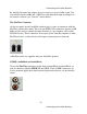
For optimal audio quality, you should adjust the input trim knob so that your
loudest recorded signal lights up the yellow light, but not the red. When the red
meter light shines extra bright – you’ve clipped! If the signal level ever exceeds
0dBFS the signal will be “clipped” and you will hear a “pop” or “tick” in the
recording. This is a very bad thing, and clipping should be avoided at all costs!
There is enough headroom so that you can be conservative in this area, and there is
no need to push the input levels right up to the edge of clipping.
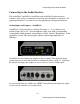
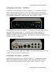
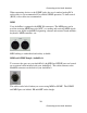
Analog Inputs and Outputs – AudioFire12
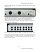
AudioFire12’s front panel has meters for the twelve analog inputs and outputs,
indicator lights for sample rate and clock synchronization, and a power button with
an amber power indicator light (not shown below).
AudioFire12 has twelve analog line inputs and twelve analog line outputs on the
rear panel. The analog inputs operate with an input impedance of 10Kohms. The
input and output connections can be used with balanced or unbalanced cables via
the ¼” connectors.
18
Connecting to the Audio Interface