
User's Manual


Console Software
30
Console Software
output bus tabs. AudioFire12 does not have S/PDIF, so it does not have a digital
output bus; it has 6 analog output bus tabs instead.
NOTE: Analog outputs 3 and 4 for the AudioFire2 are labeled as
“Headphones” in the console.
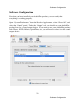
Master Output Bus Control
The master bus control is the area on the far right of the console window. It is
outlined in purple in the picture above. At the top are the labels “ANALOG”, “Out
1”, and “Out 2.” This indicates you are currently controlling everything mixed to
analog outputs 1 and 2. These channels correspond to the currently selected output
bus tab.
Beneath the labels are two green label fields that can be changed by clicking in
them and typing. Below the green label fields are nominal level buttons, mute
buttons, level meters and faders. The mute buttons and faders affect everything
being mixed to this bus. Thus, pulling the fader down will make both the input
monitors and playback quieter. The level meters display the amount of signal
being sent out of the selected outputs.
The gang button sets the gang mode. If you are in gang mode, the mute buttons
will work together for the left and right channels; for example, clicking the mute
on one channel activates the mute button on the other channel. Also, ganging ties
the faders together so they will maintain their relative placement in regard to each
other.
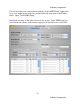
Analog Inputs
The controls for the analog inputs are on the left side of the console and have the
labels “ANALOG” and “1” through “8” at the top. They are outlined in red in the
picture above. There is one strip, or input channel, corresponding to each of
AudioFire8’s eight physical analog inputs. The input level meters remain visible at
all times, whereas the input monitor controls (pan, solo, mute, faders and gang)
that you see will change depending on which output bus is currently selected.