
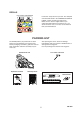
Use and Care Manual

10
CS-490
PREPARATION FOR USE
WARNING
Saw chain is sharp! Always wear gloves
when handling assembly, otherwise serious
personal injury may result.
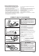
KICK GUARD
TM
TO BAR
INSTRUCTIONS
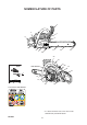
Tools Needed: Two 11 mm (7/16 in.) Wrenches.
For saws with Kick Guard
TM
P/N 2893201 and
Symmetrical Low-Kick type (Double Guard)
guide bars.
1. Install bolt (A) in rear hole (B) of Kick Guard
TM
and through front hole (C) in guide bar.
2. IMPORTANT: Dimple (D) in Kick Guard
TM
must
engage recess (E) in guide bar.
3. Tighten nut (F) and bolt (A) using 11 mm (7/16
in.) wrenches until snug. Make certain Kick
Guard
TM
is flush against guide bar.
4. Tighten nut (F) 1/8 additional turn.
5. Check to make certain Kick Guard
TM
is tight on
guide bar.
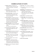
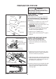
GUIDE BAR AND SAW CHAIN
INSTALLATION/REMOVAL
1. Remove spark plug lead. (See page 26)
2. Remove two clutch cover nuts and remove
clutch cover.
3. Remove bar and saw chain if necessary. See
“Maintenance and Care” section for guide bar/
saw chain maintenance procedures.
4. Unlock the chain brake, and mount guide bar on
studs and slide toward clutch to make saw chain
installation easier. Install chain with cutters on
top of guide bar facing forward.
5. Install the clutch cover over the guide bar studs.
Ensure chain tension adjuster pin fits into the
guide bar adjuster hole. Tighten clutch cover
nuts finger tight.
Clutch cover
Brake lever
(Front hand guard)
Two nuts
Unlock chain brake
Spiked bumper
Guide bar adjuster hole
Clutch cover
Nuts
Clutch Guide bar studs
Bolt (A)
Dimple (D)
Recess (E)
Front hole (C)
Rear hole (B)
Nut (F)
Guide bar
Kick Guard
TM