5SX_ LANlink Router Option User Manual WARNING - BEFORE INSTALLATION, PLEASE REFER TO SAFETY INSTRUCTIONS IN APPENDIX A, AND EMC INSTRUCTIONS IN APPENDIX C Certified Compliant in the EC, when fitted in accordance with the installation instructions, against the following directives/standards: Low Voltage Directive (73/23/EEC and amendment 93/68/EEC) EN60950 : 1992 (Safety) Electromagnetic Compatibility subsequent amendments to date): EN55022 EN50082-1 directive (89/336/EEC and : 1994 (Emissions) : 199
CONTENTS 1 INTRODUCTION.................................................................... 6 1.1 1.2 Functional Overview............................................................................. 7 Typical Applications ............................................................................. 7 2 USE AND CONFIGURATION................................................ 9 2.1 2.2 2.3 2.4 2.4.1 2.4.2 2.5 2.5.1 2.5.2 2.5.3 2.6 2.6.1 2.6.2 2.6.3 2.6.4 2.6.5 2.6.6 2.6.7 2.6.8 2.6.
.2.4 4.2.5 4.3 4.4 4.4.1 4.4.2 4.4.3 4.4.4 4.5 4.6 4.6.1 4.6.2 4.7 4.7.1 4.7.2 4.7.3 4.7.4 4.7.5 4.8 4.8.1 4.8.2 IPX: SAP TABLE ......................................................................... 27 SHOW TRAFFIC DETAILS ......................................................... 28 NETWORK LOADING ........................................................................ 28 REMOTE MANAGEMENT.................................................................. 29 TELNET OUT .................................
GLOSSARY ADPCM ARP ARPA ASCII BER BOOTP bps CHAP CRC D&I DNS EEPROM FAS GND ICMP IP IPX LAN LED MAC NCP PABX PAP PC PCM PPP RIP SAP SELV SKT SNMP TCP TDM TFTP UDP WAN Adaptive Differential Pulse-Code Modulation Address Resolution Protocol Advanced Research Projects Agency American Standard Code for Information Interchange Bit Error Rate Bootstrap Protocol bits per second Challenge Handshake Authentication Protocol Cyclic Redundancy Check Drop and Insert Domain Name Server Electrically Erasable Programmable
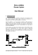
Echo LANlink Router Option User Manual 1 INTRODUCTION This user manual describes installation, configuration and operation of the Echo LANlink Multiplexer Router option, and must be referred to in conjunction with the Echo LANlink Multiplexer User Manual. The Echo LANlink is an E1 time division multiplexer (TDM) operating at 2Mbps compliant with both EUROPEAN and UK G.703 communications standards.
The Router Option card is easily configured using the management terminal connected to the Echo LANlink from either end of the link, or through Telnet at a relevant workstation either LAN. 1.1 Functional Overview The Router Option card supports both transceiver connection (AUI port) and hub (10BASE-T port) connection to a 10MHz Ethernet LAN. Ethernet frames are transported to/from the remote LAN using some or all of the main communications link bandwidth.
the Branch Office could access the Headquarters General Server via the Echo LANlink, but accesses to the Finance Server could be stopped using subnet masking in the Echo LANlink. Figure 2 Restrictive Firewall Example In addition to the features of the router, all the existing functions of the Echo LANlink are still available.
2 USE AND CONFIGURATION This section covers connection and set-up of the Echo LANlink Router Option, and must be used in conjunction with the Echo LANlink User Manual. If you are not familiar with the general configuration procedure for the Echo LANlink, please refer to that manual before reading further and attempting to configure the Router Option. 2.
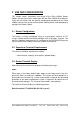
If you are using a terminal from this list type y , or alternatively press n to enter another type: supported terminal types are shown in Figure 3 - type one of them in to select a suitable terminal type and press VT100 VT220 VT320 VT420 FALCO Figure 3 SUNVIEW SUN WYSE50 A210 TVI925 TVI910 Supported Terminal Types Once a terminal type has been selected, the main menu screen shown in Figure 4 will be displayed.
2.4 Router Management Selecting ROUTER MANAGEMENT from the main menu allows the user to configure the router. The router management screen is shown in Figure 5. Refer to Section 4 for details on each menu option.
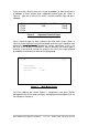
+-------------------------------------------------------------------------------+ | WAN IP FILTER 1 - WAN IP FILTER 1: S1234 EXIT | | ADD EDIT DELETE CLEAR NAME | +-------------------------------------------------------------------------------+ ENTER THE SOURCE I.P. ADDRESS (RETURN = ALL): LINE SRC ADDR SRC MASK DEST ADD DEST MASK PROT S.PRT D.PRT RSLT Figure 6 Entering a Parameter Echo LANlink Router Option User Manual Issue 1.
2.5 Multiplexer Management Selecting MULTIPLEXER MANAGEMENT from the main menu allows the user to configure the multiplexer functions. If another user is currently accessing the multiplexer management page (e.g. via a Telnet session) this will be indicated next to the menu item. Only one session is allowed access to the multiplexer functions at any one time. If NONE is displayed the user is free to enter multiplexer management.
Figure 8 shows an example timeslot set-up with 512Kbps allocated to channel 1, 320Kbps allocated to channel 2, and 1152Kbps allocated to the router. 2 MEGABIT E1 MULTIPLEXER V1.
2.6.1 MAIN LINK CARRIER LOSS The local Multiplexer cannot identify a valid synchronisation sequence (FAS, CRC4 etc) from the remote multiplexer. 2.6.2 D/I CARRIER LOSS The Multiplexer cannot identify a valid synchronisation sequence (FAS, CRC4 etc) from the unit attached to the D&I port. 2.6.3 REMOTE ALARM The unit attached to the D&I port is generating an alarm in the framing information, that is, it is reporting that it has a problem. 2.6.
2.6.9 ROUTER WAN LINK STATUS The status of the link between the two routers is displayed. Echo LANlink Router Option User Manual Issue 1.
3 INSTALLATION WARNING – Refer to Appendix A for Safety Instructions. WARNING - The multiplexer must be disconnected from the power supply and all peripheral connections before opening. 3.1 Opening the Multiplexer With the power cord and all peripherals DISCONNECTED, the screws on the left, right and top of the multiplexer are removed using a Pozidrive screwdriver to gain access to the interior of the multiplexer.
3.2 Internal Link LK13 Locate the internal connector LK13 on the motherboard (refer to Figure 9). This will be fitted with shorting links if the Echo LANlink was supplied without the Router Option. Remove the shorting links before fitting the Router Option. The links may be repositioned on one pin for storage. 3.3 Installing the Router Option Remove the option blanking plate above the CH 1 and CH2 connectors on the rear panel of the multiplexer. The blanking plate may be discarded if not required.
3.4 Testing Replace the cover and screws before powering up the unit. Correct installation of the Router Option may be confirmed by the login prompt (see section 2.3) appearing on the terminal screen. If the red error LED on the front panel is on, this indicates hardware fault has occurred. In this case, disconnect the power cable and check the installation of the Router Option is correct. 3.
3.7 Quick Configuration The first stage in configuration is to allocate some bandwidth of the communication link to the router. The second stage is to configure the SERVICE SETUP to allow communication between the two routers. 3.7.1 Multiplexer Configuration From the main menu enter MULTIPLEXER MANAGEMENT. Allocate bandwidth to the router by entering ‘R’ in any free timeslot positions near the bottom of the screen. Each timeslot allocated will contribute 64Kbps of bandwidth to the router.
3.7.2.4 Receive IP RIP To enable routes to destinations within the local network to be added to the routing table this field should be set to the appropriate protocol; NONE, RIP1, RIP2 or both RIP1 and RIP2. If the RIP version is unknown then set BOTH. 3.7.2.5 Transmit IP RIP To allow the Router to propagate routes learnt from the WAN to the local network, this field must be set to the correct value for the RIP protocol being used or to NONE to disable RIP transmission.
3.7.2.11 Receive IPX RIP Set this field to YES to receive IPX RIP responses from other routers or servers on the local network. 3.7.2.12 Transmit IPX RIP Set this field to YES to transmit regular IPX RIP responses to other routers or servers on the local network. If set to NO, IPX RIP responses will only be sent as a result of receiving a RIP request. 3.7.2.13 Receive IPX SAP Set this field to YES if you wish to receive IPX SAP responses from other routers or servers on the local network.
4 ROUTER MENU OPTIONS The menu options allow the user to configure the router to individual requirements. The menu tree is shown in the diagram below, and each option is discussed in the following section. Login Prompt Router Management Unit Status Traffic Analysis Multiplexer Management Network Loading Remote Management Unit Configuration System Status Service Setup Filter Setup Events 4.1 UNIT STATUS This option displays statistics for the Ethernet and WAN links.
PARAMETER OTHER MODE Rx PACKET COUNT Rx PACKET ERROR Tx PACKET COUNT Tx PACKET OVERFLOW LINE SPEED DESCRIPTION OPTIONS Current OTHER BLOCK protocol routing status BRIDGE Number of packets seen on the segment connected to the port displayed. Number of packets received with CRC or Frame errors. Number of packets transmitted by Router. Number of packets discarded by Router owing to queue time exceeding the permitted maximum delay.
routing table. Turning off IP RIP Receive as before will cause other learned routes to age out after about four minutes. PARAMETER NETWORK SUBNET BITS/MASK GATEWAY SERVICE TIMER METRIC DESCRIPTION The IP Network number to which this RIP entry relates. This shows the subnet mask detected by the Router. The IP Address of the next gateway used in this route to send a packet to the specified network. The required service that must be used to reach a specified network.
4.2.3 IPX: RIP TABLE This table displays the current IPX routes in the IPX RIP table. Information in this table comes from four sources: 1. The IPX network number determines which network is physically attached to the Ethernet port. 2. IPX SAP Packets received from the Ethernet Port. 3. IPX SAP Packets received from the WAN port. 4. Static (permanent) entries entered by the user. The user can define up to 16 static routes in this table.
4.2.4 IPX: SAP TABLE This table displays the IPX services in the IPX SAP table. Information in this table comes from three sources: 1. IPX SAP Packets received from the Ethernet Port. 2. IPX SAP Packets received from the WAN port. 3. Static entries entered by the user. The user can define up to 16 static routes in this table. The simplest means to allow the router to 'learn' available services is to use IPX SAP Receive. For configuration see the Ethernet Service Setup section.
4.2.5 SHOW TRAFFIC DETAILS Displays a list of the current traffic received by the router. PARAMETER ADDRESS AGE FLAGS DESCRIPTION MAC address Time since packet last received L = local to the attached LAN H = addressed to this unit 4.3 NETWORK LOADING This option shows the load on the WAN and Ethernet ports over five second, one minute and five minute periods.
4.4 REMOTE MANAGEMENT Selecting the Remote Management menu presents the user with the following four options. Unit Status Traffic Analysis Network Loading Remote Management Telnet Out Name Server Configuration Security SNMP Security Unit Configuration Service Setup Filter Setup Events View Name to IP Cache 4.4.1 TELNET OUT This option will enable telnet connection, by entering the relevant IP Address, to a remote workstation. 4.4.
4.4.2.1 NAME TO IP CACHE PARAMETER IP ADDRESS NAME TIMER DESCRIPTION The name server IP address. The name associated to this IP address. If a name request is made to the DNS it will allocate a time period to retain the information. The timer shows how much time remains. 4.4.3 SECURITY PARAMETER CHANGE USER PASSWORD DESCRIPTION Allows user to change password. Old password must be entered prior to acceptance. OPTIONS USER PASSWORD User password access control.
PARAMETER READ CONFIGURATION FROM DESCRIPTION Access permission to read configuration from the Router from external source. OPTIONS NONE ANY IP ADDRESS IP NAME EXTERNAL LOGIN UNIT External control unit access ENABLE DISABLE 4.4.4 SNMP SETUP PARAMETER COMMUNITY CONTACT NAME EQUIPMENT LOCATION SEND SNMP TRAPS TO DESCRIPTION SNMP Community: default PUBLIC Responsible for equipment. Useful to give telephone number. Allows rapid location of equipment when required. IP addresses of four SNMP stations.
4.6 SERVICE SETUP Unit Status Traffic Analysis Network Loading Remote Management Unit Configuration Ethernet Service Service Setup Filter Setup Events WAN Service PPP Setup PARAMETER ETHERNET SERVICE DESCRIPTION Brief summary of the LAN service available, including IP and IPX addresses as appropriate. Summary of traffic filters in use on WAN link. WAN SERVICE 4.6.
PARAMETER IP BROADCAST IP FILTER MAC FILTER IPX NETWORK IPX FRAME RECEIVE IPX RIP TRANSMIT IPX RIP RECEIVE IPX SAP TRANSMIT IPX SAP IPX SAP FILTER DESCRIPTION IP Broadcast Packet structure Enable or disable the IP Filter Table defined for the Ethernet port. N.B. If the IP filter table has no entries then all IP packets are ignored if enabled Enables or disables MAC filtering The Network number of the attached IPX network.
4.6.2 WAN SERVICE SETUP PARAMETER SERVICE NAME COMPRESSION LINE PROTOCOL MAC FILTER IP MODE IP RIP UPDATES BOOTP PROCESSING IP HOPS IP FILTER IPX MODE IPX RIP UPDATES IPX SAP UPDATES PROPOGATE NETBIOS IPX HOPS IPX TICKS IPX SAP FILTER DESCRIPTION WAN service name. Router compression facility Multi-vendor compatibility option. MAX filter capacity OPTIONS User defined.
PARAMETER OTHER 4.6.2.1 DESCRIPTION Controls bridging other protocols. OPTIONS of BRIDGE BLOCK PPP SETUP Authentication is not normally used on leased lines. PARAMETER DESCRIPTION Required By Remote Router/Service AUTHENTICATION TYPE Type of authentication required by remote router to accept connection. N.B. CISCO equipment will not negotiate so PAP or CHAP is unacceptable.
4.7 FILTER SETUP N.B. IP and IPX filter tables are created using these menus BUT are activated using the SERVICE SETUP menu. Unit Status Traffic Analysis Network Loading Remote Management Unit Configuration MAC Filter Ethernet MAC Filter WAN MAC Filter Service Setup Events IPX SAP Filter IP Filter Ethernet IP FIlter Filter Setup WAN MAC FIlter Ethernet IPX SAP Filter WAN IPX SAP Filter There are filter tables available for both the Ethernet connection and WAN link.
4.7.2 IP FILTER (WAN or Ethernet) Both the Ethernet and WAN ports on the router can have an individual IP filter table. If IP filtering is active then any packets received are checked against the filter table before processing by the Router. Each port IP filter table can have 64 entries. When the first entries are made they will not become active until the table screen is exited. Any future input will become active immediately.
MENU SELECTION SRC MASK DEST ADDR DEST MASK PROT S.PRT D.PRT DESCRIPTION The IP mask associated with the Source Address in hexadecimal format. Left blank if ALL source addresses are forwarded. The destination address of IP packets to be filtered. A network address, individual IP address or ALL may be specified. The IP mask associated with the Destination Address in hexadecimal format. Left blank if ALL destination addresses are specified. Indicated the protocol this entry will filter on e.g.
This is the source IPX network number of the service. Services will not be entered into the internal SAP table if the RIP table has no entry for the route to this address. Node Address (48 bits) This is the Ethernet or Token Ring MAC address from where the SAP originated. Hops (16 bits) This is the number of Routers that must be traversed to reach this service. Every time this SAP passes another Router this count is incremented to a maximum of 16.
4.7.4 IPX HEADER FILTERS There is a single IPX header filter that can control the forwarding of packets from each port. The user can select if this filter is applied to packets received from either or both ports. The filter can have up to 128 entries. If IPX filtering is active, then any packets received are checked against the filter table before processing by the Router. The operation of the IPX filter does not effect RIP and SAP packets as they are processed directly by the Router.
MENU SELECTION NETWORK MAC NODE ADR SOCKET P.T RSLT DESCRIPTION Source or destination IPX number (eight digit hexadecimal.) Ethernet MAC address of the network adapter card (twelve digit hexadecimal. File servers are usually designated 000000000001. Designates a conversation between two addresses. An 8-bit field that specifies the upperlayer protocol to receive the packet's information e.g. NCP or SPX. The action to be taken as a result of IPX packets meeting filter conditions e.g.
Unit Status Traffic Analysis Network Loading Remote Management Unit Configuration Service Setup Filter Setup Events PPP Events System Events This menu option allows the user to display significant event activity for the Router. These displays are intended for use as diagnostic tools for engineers or planning aids for the network manager. 4.8.1 PPP EVENTS This display shows connection ‘conversations’ held between the local Router and remote equipment allowing quick and effective fault diagnosis.
FLASH ERASE ERROR PARAMETER x FLASH PROGRAMMING TIMEOUT FLASH VERIFY ERROR COMPRESSION ERROR HISTORY x STATUS y COMPRESSION TIMEOUT HISTORY x STATUS y DECOMPRESSION ERROR HISTORY x STATUS y DECOMPRESSION TIMEOUT HISTORY x STATUS y Echo LANlink Router Option User Manual Issue 1.
APPENDIX A WARNINGS WARNING: THIS EQUIPMENT GROUNDED MUST BE EARTHED/ This equipment relies on the EARTH / GROUND connection to ensure safe operation such that the user and TELECOM Network are adequately protected. It must not under any circumstances be operated without an earth connection, which could nullify its approval for connection to a network. WARNING: INSTALLATION OF EQUIPMENT Installation of this equipment must only be performed by suitably trained service personnel.
Warnung: Dieses Gerät Muß an einem Anschluß mit Schutzleiter betrieben werden. Zum sicheren Betrieb ist der Anschluß des Gerätes an Spannungsversorgungen mit Schutzleiter notwendig. Nur so kann ein optimaler Schutz für Bedienpersonal und Übertragungseinrichtungen gewährleistet werden. Unter keinen Umständen darf dieses Gerät ohne Schutzleiter betrieben werden, da ansonsten die Zulassung für den Anschluß an Netzen erlischt.
Mise en garde: Cet équipement doit être relié a la terre Cet équipement doit posséder une prise de terre de manière à ce que le réseau télécom et ses utilisateurs soient équitablement protégés. Tout manquement à cette obligation entraînerait l'annulation de l'autorisation de connexion a un réseau. Mise en garde: Installation de l'équipment L'installation doit être assurée uniquement par des personnels convenablement formés à ce type de matériel.
APPENDIX B APPROVAL REQUIREMENTS There are no specific approval requirements for the Router Option - refer to Echo LANlink User Manual for general approval requirements. Echo LANlink Router Option User Manual Issue 1.
APPENDIX C EMC REQUIREMENTS There are no specific EMC requirements for the Router Option - refer to Echo LANlink User Manual for general EMC requirements. Echo LANlink Router Option User Manual Issue 1.
APPENDIX D REAR PANEL LAYOUT The layout of all ports on the rear panel of the Echo LANlink with Router Option fitted is shown in the diagram below: Echo LANlink Router Option User Manual Issue 1.
APPENDIX E AUI PORT (15-WAY D-TYPE) PINOUT The AUI port connector is a 15-pin, D-type socket.
APPENDIX F 10BASE-T (RJ45) PORT PINOUT The twisted-pair Ethernet port connector is a 8-pin, RJ45 socket, conforming to the 10BASE-T standard and suitable for connection to an Ethernet hub.
APPENDIX G IP FILTER EXAMPLES If IP filtering is active then all packets received are checked against the filter table before processing by the Router. Packets are also compared to the IP Filter Table when the IP Filter is set to Bridge. The IP Filter can have 32 lines or entries. An entry does not initially become active until the user exits the menu. Future amendments are acted upon immediately after entry.
G.1.1 Examples To pass any packet coming from the Class A 89.0.0.0 network you would enter: SRC ADDR 89.0.0.0 SRC MASK FF000000 The mask of FF00000 limits the comparison to the first 8 bits of the incoming address. If a Class B address of 130.140 has a subnet with 8 bits to provide the network/subnet of 130.140.5, then to filter any packet from this subnet you would enter: SRC ADDR 130.140.5.
Ports can be given a specific value or the user can use wildcards to pass all values. Various services use a specific port number e.g. Telnet uses Port 23, FTP uses port 21. RFC 1700 gives a list of standard port values. G.3.1 Examples If 130.140.5.10 wishes to be able to Telnet to 130.140.6.32, but does not wish 130.140.6.32 to be able to Telnet back to him the following line should be used: SRC ADDR 130.140.5.10 SRC MASK FFFFFFFF DEST ADDR 130.140.6.32 DEST MASK FFFFFFFF PROT TCP S.PRT ALL D.
APPENDIX H IP SUBNETS An Internet Protocol (IP) address is 32 bits long and is split into two parts. The first part is the network number and the second part is the unit number. Combined they make a unique address. An address with a different network number can only be reached via a Router. The way the IP address is split into these two parts varies on the upper bits of the network number. This fixed split is defined as three classes.
APPENDIX I ROUTER MAINTENANCE MENU For security reasons the Multiplexer must be directly connected to a terminal to access the MAINTENANCE MENU. Login to the unit as CMGR at the initial prompt. All access passwords will apply as usual. On login a $$ prompt will appear. Type UPGRADE MENU . The prompt ARE YOU SURE? will appear. Type YES and the MAINTENANCE MENU will appear. I.1 KERMIT A new version of the Router firmware may be downloaded to flash memory via the console port using Kermit.
Erasing Flash Memory Programming Flash Memory Verifying Flash Memory Flash Memory OK AN8100B Small Office Server Maintenance Menu Vx.x 1) Update Flash from Console port with Kermit 2) Update Flash from Ethernet with TCP Loader 3) Update Flash from Ethernet with TFTP Loader 4) Restore configuration from Ethernet via TFTP 6) Set new IP Address (xx.xx.xx.xx) 7) Set default Gateway (xx.xx.xx.
I.5 Set New IP Address Selecting this option will allow the Manager to set a new IP address for the Router if required to facilitate the file transfer. Note the burnt in MAC address will be used in the Maintenance mode. I.6 Set Default Gateway Selecting this option will allow the Manager to set a default gateway (should RIP not be transmitted) for the Router if required to facilitate the file transfer. I.7 Run Flash Program This will reboot the Router. I.
I.10 Boot File Using TFTP Loader This option will remotely upgrade the BOOT code. The program is loaded into RAM and executed. Selecting this option will allow the Manager to TFTP download the firmware upgrade to the Router. The Router will act as a server, enabling the files to be downloaded from the PC in a Binary or Octet formats (not ASCII.) I.11 Run Monitor This will enable the factory to monitor memory functions within the Router. Echo LANlink Router Option User Manual Issue 1.