POWER PRUNERTM OPERATOR'S MANUAL 1 Power PrunerTM Operator's Manual MODELS: PPF-2100 TYPE 1/1E Serial Number 001001 - 001162 PPF-2110 TYPE 1/1E Serial Number 001001 - 001016 WARNING The engine exhaust from this product contains chemicals known to the State of California to cause cancer, birth defects or other reproductive harm. WARNING DANGER Read rules for safe operation and instructions carefully. ECHO provides an Operator's Manual and a Safety Manual.
INTRODUCTION Welcome to the ECHO family. This ECHO product was designed and manufactured to provide long life and on-the-jobdependability. Read and understand this manual and the SAFETY MANUAL you found in the same package. You will find both easy to use and full of helpful operating tips and SAFETY messages. WARNING DANGER Read rules for safe operation and instructions carefully. ECHO provides an Operator's Manual and a Safety Manual. Both must be read and understood for proper and safe operation.
POWER PRUNERTM OPERATOR'S MANUAL 3 MANUAL SAFETY SYMBOLS & IMPORTANT INFORMATION Throughout this manual and on the product itself, you will find safety alerts and helpful, information messages preceded by symbols or key words. The following is an explanation of those symbols and key words and what they mean to you. This symbol accompanied by the words WARNING and DANGER calls attention to an act or condition that can lead to serious personal injury to operator and bystanders.
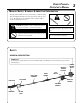
DECALS Locate this safety decal on your unit. The complete unit illustration found in the "DESCRIPTION" section, will help you locate them. Make sure the decals are legible and that you understand and follow the instructions on them. If a decal cannot be read, a new one can be ordered from your ECHO dealer. See PARTS ORDERING instructions for specific information.
POWER PRUNERTM OPERATOR'S MANUAL Guide Bar and Saw Chain WARNING DANGER • Serious injury may result from the use of non approved guide bar and saw chain combinations. Read and comply with all safety instructions listed in this manual. • ECHO, INC. will not be responsible for the failure of cutting devices or accessories which have not been tested and approved by ECHO for use with this unit. • Check that the cutting attachment, guide bar and saw chain is firmly attached and in safe operating condition.
PERSONAL CONDITION & SAFETY EQUIPMENT WARNING DANGER Power PrunerTM users risk injury to themselves and others if the Power PrunerTM is used improperly and or safety precautions are not followed. Proper clothing and safety gear must be worn when operating a Power PrunerTM. Physical Condition -Your judgment and physical dexterity may not be good: • if you are tired or sick, • if you are taking medication, • if you have taken alcohol or drugs. Operate unit only if you are physically and mentally well.
POWER PRUNERTM OPERATOR'S MANUAL SAFE OPERATION WARNING DANGER All over head electrical conductors and communications wires can have electricity flow with high voltages. Never touch wires directly or indirectly when pruning, otherwise serious injury or death may result. Determine Operation Area • Provide all operators of this equipment with the Operator's Manual, and instructions for safe operation. • Do not operate this product indoors or in inadequately ventilated areas.
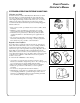
Keep A Firm Grip • Grip Power PrunerTM with both hands with thumbs and fingers encircling the handle, and shaft tube. Keep A Solid Stance • Maintain footing and balance at all times. Do not stand on slippery, uneven or unstable surfaces. Do not work in odd positions or on ladders. Do not overreach. • Operate the Power PrunerTM only from the ground or out of an approved bucket lift.
POWER PRUNERTM OPERATOR'S MANUAL EXTENDED OPERATION/EXTREME CONDITIONS Vibration and Cold It is believed that a condition called Raynaud’s Phenomenon, which affects the fingers of certain individuals may be brought about by exposure to vibration and cold. Exposure to vibration and cold may cause tingling and burning sensations followed by loss of color and numbness in the fingers. The following precautions are strongly recommended because the minimum exposure which might trigger the ailment is unknown.
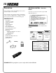
DESCRIPTION EMISSION CONTROL - Emissions Models Due to packaging restriction the ECHO product you have purchased requires some assembly. After opening the carton, check for damage. Immediately notify your retailer or ECHO Dealer of damaged or missing parts. Use the contents list to check for missing parts.
POWER PRUNERTM OPERATOR'S MANUAL 22 PPF-2100 PPF-2110 23 24 21 20 19 14 18 17 16 15 1 6 8 3 2 5 4 7 13 9 12 10 11 25 11
1. POWER HEAD - Includes the Engine, Clutch, Fuel System, Ignition System and Starter. 2. REAR HANDLE ASSEMBLY - Rear (right hand) handle. 3. THROTTLE TRIGGER LOCKOUT - This lever must be held during starting. Operation of the throttle trigger is prevented unless throttle trigger lockout lever is engaged. 4. STOP SWITCH - Mounted on top of rear handle assembly. Move switch forward to run, back to stop. 5. STRAP HOOK - Used to secure unit to shoulder harness. 6.
POWER PRUNERTM OPERATOR'S MANUAL 13 SPECIFICATIONS MOD EL PPF-2100 PPF-2110 2.39 m (7 ft, 10 i n.) Length 3.30 m (10 ft, 10 i n.) Length w/Opti onal 3 ft. extensi on Wi dth 0.22 m (8.75 i n.) Hei ght 0.23 m (9.0 i n.) Wei ght (dry) Engi ne Type 5.91 kg (13.0 lb.) 6.9 kg (15.2 lb.) Ai r cooled, two-stroke, si ngle cyli nder gasoli ne engi ne 32.2 mm (1.268 i n.) Bore 26.0 mm (1.04 i n.) Stroke 21.2 cc (1.29 cu. i n.
ASSEMBLY For your convenience the Power PrunerTM has been shipped with the power head attached and throttle linkage assembled. We recommend the power head remain attached to the drive shaft and housing at all times. CUTTING ATTACHMENT TO DRIVE SHAFT INSTALLATION Tools Required: 3 mm Hex Wrench Parts Required: Power Head/Drive Shaft; Cutting Attachment WARNING DANGER Saw chain is sharp! Always wear gloves when handling cutting attachment, otherwise serious personal injury may result. 1.
POWER PRUNERTM OPERATOR'S MANUAL 1. 2. Remove the cutting attachment from the Power PrunerTM shaft housing by removing the location bolt (B), loosening the (4) four lower bolts (A) clamping the cutting attachment to the shaft housing and slide the cutting attachment off. B Loosen the 4 screws (D) on the extension clamp and slide the extension onto the shaft housing until the hole (E) in the extension clamp lines up with the hole (C) in the shaft housing. Insert the #8 x 1/2 in.
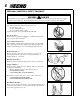
PRE-OPERATION FUEL Fuel Requirements Gasoline - Use 89 Octane [R +2 M ] gasoline or gasohol known to be good quality. Gasohol may contain up to 10% Ethyl (grain) alcohol or 15% MTBE (methyl tertiary-butyl ether). Gasohol containing methanol (wood alcohol) is NOT approved. Two-Stroke Oil - A two-stroke engine oil meeting ISO-L-EGD Standard (ISO/CD 13738), must be used. Echo brand Premium 50:1 oil meets this standard.
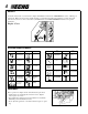
POWER PRUNERTM OPERATOR'S MANUAL IMPORTANT Stored fuel ages. Do not mix more fuel than you expect to use in thirty (30) days, ninety (90) days when a fuel stabilizer is added. IMPORTANT Stored two-stroke fuel may separate. ALWAYS shake fuel container thoroughly before each use. S M 1 2 8 9 15 16 22 23 29 30 T 3 10 17 24 31 LUBRICATING THE GUIDE BAR AND SAW CHAIN Automatic Oiling System 1. Wipe debris from around oil fill cap. 2.
EQUIPMENT CHECK Before operation a complete check of the unit must be performed; • Check unit for loose/missing nuts, bolts and screws. Tighten and/or replace as needed. • Inspect fuel lines, tank and area around carburetor for fuel leaks. DO NOT operate unit if leaks are found. • Check that the cutting attachment is firmly attached and the saw chain is correctly tensioned on the guide bar. Dull, loose or damaged saw chain should not be used. Refer to page 29 for correct Filing Saw Chain procedure.
POWER PRUNERTM OPERATOR'S MANUAL OPERATION WARNING DANGER Do not operate this product indoors or in inadequately ventilated areas. Engine exhaust contains poisonous emissions which can cause serious injury or death. • Provide all operators of this equipment with the Operator's Manual, and instructions for safe operation. • Before starting the unit, equip yourself and any other person working within the 15 M (50 ft.) Safety Zone with the required Protective Equipment and clothing.
5. After engine fires (or five [5] pulls), move choke lever back to “Run” position. Hold throttle trigger and throttle trigger lockout fully depressed and pull recoil starter handle/rope until engine starts and runs. Release throttle trigger and allow unit to warm up at idle for several minutes. NOTE If engine does not start with choke in “Run” position after 5 pulls, repeat instructions. 6. After engine warm up, gradually depress throttle trigger to increase engine RPM to operating speed.
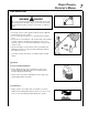
POWER PRUNERTM OPERATOR'S MANUAL 21 PRUNING TECHNIQUES The Power PrunerTM is designed for light to medium trimming of limbs and branches up to 203mm (8 in.) in diameter. Follow these tips for successful operation. CORRECT • Plan cut carefully. Check direction branch will fall. • Plan retreat path from falling branch. Cut branches bounce when striking ground. • Long branches should be removed in several pieces. GUIDE AGAINST BRANCH NOT CORRECT • Do not stand directly beneath branch being cut.
MAINTENANCE INTERVALS COMPONENT/ SYSTEM MAINTENANCE PROCEDURE REQ'D SKILL LE V E L DAILY OR BEFORE U SE EVERY R E FU E L 3 MONTHS OR 90 HOURS 6 MONTHS OR 270 HOURS YEARLY 600 HOURS Recommended Echo Dealer Maintenance Procedures Cylinder Exhaust Port Inspect/Clean/Decarbon 3 I/C Do-It-Yourself Maintenance Procedures Air Filter Inspect/Clean/Replace 1 I/C Choke System Inspect/Clean 2 I/C Fuel Filter Inspect/Replace 1 Fuel System, leaks Inspect/Replace 1 I/R* Cooling System Insp
POWER PRUNERTM OPERATOR'S MANUAL AIR FILTER Level 1. Tools Required: 25mm or 50mm (1 in. or 2 in.) medium bristle paint brush Parts required: . 90008 REPOWERTM AIR & FUEL FILTER KIT. 1. Close choke (Cold Start Position). This prevents dirt from entering the carburetor throat when the air filter is removed. Brush accumulated dirt from the air cleaner area. 2. Remove the air cleaner cover. Clean and inspect the element for damage. If element is fuel soaked and very dirty, replace. 3.
SPARK PLUG Level 2. Tools Required: 10x19mm (13/32x3/4in.) T-wrench, Feeler gauge, (preferably a wire gauge), Soft metal brush Parts Required: Spark Plug, NGK BPMR-7A; P/N 15901010230 1. Remove spark plug and check for fouling, worn and rounded center electrode. 2. Clean the plug or replace with a new one. DO NOT sand blast to clean. Remaining sand will damage engine. 3. Adjust spark plug gap by bending outer electrode. 4. Tighten spark plug to 145-155 kg/cm (125-135 in. lb.). 0.65 mm (0.026 in.
POWER PRUNERTM OPERATOR'S MANUAL 3. Use the wooden stick or brush to remove dirt from cylinder fins. 4. Remove grass and leaves from the grid between the recoil starter and fuel tank. 5. Assemble components in reverse order. NOTE When installing the engine cover, be certain the tab of the metal deflector shield is in the slot of the engine cover. EXHAUST SYSTEM Spark Arrestor Screen Level 2.
CARBURETOR ADJUSTMENT Emission Models Level 2. Tools Required: Screwdriver with 2mm blade width, Tachometer (ECHO P/N 99051130017) Parts required: None. NOTE Every unit is run at the factory and the carburetor is set in compliance with EPA Phase 1 and California Emission Regulations. In addition, the carburetor is equipped with HI (A) and LO (B) needle adjustment limiters that prevent settings outside acceptable limits. 1.
POWER PRUNERTM OPERATOR'S MANUAL 27 CARBURETOR ADJUSTMENT Non Emissions Models Level 2 Tools Required: Screwdriver with 2mm blade width, Tachometer (ECHO P/N 99051130017) Parts required: None. NOTE If carburetor has limiter caps follow "Carburetor Adjustment" procedures for Emission models on previous page. Idle Speed Adjustment Turn "idle" speed adjustment screw (C) CW (clockwise) until cutting attachment begins to turn, then turn screw out CCW (counter clockwise) until cutting attachment stops turning.
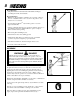
GUIDE BAR AND SAW CHAIN REPLACEMENT WARNING DANGER Never try to replace or adjust guide bar and saw chain with engine running. This saw chain is VERY sharp, wear heavy gloves to protect your hands when handling it. Wear eye protection meeting CE or ANSI specification Z87.1. Guide Bar Replacement / Installation Level 3 Tools Required: 10x19mm (13/32x3/4 in.) T-Wrench • Remove two (2) 10 mm (13/32 in.) guide bar nuts (A) and relieve saw chain tension turning screw (B) counter clockwise.
POWER PRUNERTM OPERATOR'S MANUAL 29 FILING SAW CHAIN Level 3. Tools Required: 4.5 mm round File P/N 89751001130; Flat File P/N 89751100230; Depth Gauge P/N 89751400232. IMPORTANT Dull or damaged cutters will result in poor cutting performance, increased vibration and premature saw chain failure. WARNING DANGER Always stop engine and wear gloves when filing saw chain, otherwise serious personal injury may result. 1. Set round file (A) in cutter at 30° angle.
TROUBLESHOOTING Problem Engine starts hard does not start Engine Cranks Cause Remedy Fuel strainer clogged Fuel line clogged Carburetor Carburetor Clean Clean See your Echo dealer See your Echo dealer Muffler wet with fuel Fuel mixture is too rich Spark at end of plug wire No spark at end of plug wire Stop switch off Electrical problem Interlock switch Open choke Clean/replace air filter Adjust carburetor See your Echo dealer Turn switch on See your Echo dealer See your Echo dealer Spark at pl
POWER PRUNERTM OPERATOR'S MANUAL STORAGE Long Term Storage (over 30 days) Do not store your unit for a prolonged period of time (30 days or longer) without performing protective storage maintenance which includes the following: 1. Store unit in a dry, dust free place, out of the reach of children. WARNING DANGER Do not store in enclosure where fuel fumes may accumulate or reach an open flame or spark or serious personal injury may result. 2. Place the stop switch (A) in the "OFF" position. 3.
SERVICING INFORMATION PARTS Genuine ECHO Parts and ECHO REPOWERTM Parts and Assemblies for your ECHO products are available only from an Authorized ECHO Dealer. When you do need to buy parts always have the Model Number, Type number and Serial Number of the unit with you. You can find all three numbers on the engine housing. For future reference, write them in the space provided below. Model No. ____________Type No. ____________ SN.