GB ENGLISH D DEUTSCH I ITALIANO OPERATOR’S MANUAL BEDIENUNGSANLEITUNG MANUALE D’ISTRUZIONI RM-4000 RM-4000SI RM-5000 WARNING DANGER GB READ INSTRUCTIONS CAREFULLY AND FOLLOW RULES FOR SAFE OPERATION. FAILURE TO DO SO COULD RESULT IN SERIOUS INJURY. ACHTUNG GEFAHR D LESEN SIE DIE BEDIENUNGSANLEITUNG SORGFÄLTIG DURCH UND BEFOLGEN SIE DIE SICHERHEITSBESTIMMUNGEN, WEIL SONST DAS RISIKO SCHWERER VERLETZUNGEN BESTEHT.
INTRODUCTION ECHO Grass Trimmers/Brushcutters are lightweight, highperformance, petrol engined units designed for weed control, grass trimming and brush cutting in areas difficult to control by any other means. This Manual provides the information necessary for assembly, operation and maintenance. You must read this Manual to understand the safe and effective operation of your ECHO product. CONTENTS E N G L I S H Introduction ................................................................
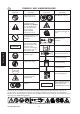
DECALS AND SYMBOLS GB Symbol form/shape Symbol description/application Symbol form/shape Symbol description/application Carefully read the operator’s manual Usage of metal blades not permitted This symbol accompanied by the words WARNING and DANGER calls attentions to an act or a condition which can lead to serious personal injury or death. Warning, side thrust The maximum speed of the cutting attachment shaft in r/min Circle and slash symbol means whatever is shown is prohibited.
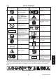
SYMBOLE UND HINWEISSCHILDER D Symbolform E N G L I S H Symbolbeschreibung/anwendung Symbolform Achtung Die Bedienungsanleitung sorgfältig durchlesen Verwendung von Metallklingen verboten! Dieses Symbol weist in Verbindung mit den ACHTUNG und GEFAHR auf eine Handlung oder einen Zustand hin, die schwerwiegende Körperverleztung verursachen können.
DECALCOMANIE I Forma del simbolo Descrizione/ applicazione del simbolo Forma del simbolo AVVERTENZA. VEDERE IL MANUALE DELL’OPERATORE Vietato l’uso di lame metalliche Questo simbolo accompagnato dalle diciture AVVERTENZA e PERICOLO, richiama l’attenzione su un’azione o condizione che potrebbero provocare gravi lesioni personali o la morte.
E N G L I S H D E U T S C H I T A L I A N O RULES FOR SAFE OPERATION Operator’s manual Do not permit operation without proper training and protective equipment. TRAINING WARNING Read the Operator’s Manual carefully. Be thoroughly familiar with the controls and proper use of the unit. DANGER GRASS TRIMMERS AND BRUSHCUTTERS CAN THROW SMALL GRAVEL, STONE, GLASS, METAL OR PLASTIC OBJECTS AS WELL AS THE MATERIAL BEING CUT. READ THESE “RULES FOR SAFE OPERATION” WITH CARE.
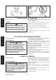
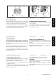
1 2 Wear eye protection 1. Earmuffs EYE PROTECTION 2. Earplugs The operator must wear eye protection not only against objects thrown by the unit, but also because eye infections can be caused by airborne dust, seeds and pollen. HEARING AND EAR PROTECTION Prescription glasses may be worn under the safety goggles. Wear a suitable hearing protective device such as earmuffs or earplugs to protect against objectionable or uncomfortable loud noises.
2 1 3 4 5 6 7 8 1. 2. 3. 4. PROTECTIVE CLOTHING E N G L I S H D E U T S C H Choose trousers, shirts and jackets that fit trimly and have no strings, frills or dangling straps which could catch on the unit or the underbrush. Do not wear ties, loose clothing or jewellery. Keep clothing buttoned or zipped up and shirt tails tucked in. Secure hair so it is above shoulder length. 5. 6. 7. 8.
WARNING DANGER IN ADDITION TO HEAD, EYE AND EAR PROTECTION WEAR PROTECTIVE CLOTHES, SAFETY GLOVES AND SHOES TO PROTECT YOUR FEET AND BODY FROM THROWN OBJECTS, AND IMPROVE YOUR FOOTING ON SLIPPERY SURFACES. DO NOT WEAR TIES, JEWELLY, OR LOOSE, DANGLING CLOTHING WHICH COULD BE CAUGHT IN THE UNIT. DO NOT WEAR OPENTOED FOOTWEAR, OR GO BARE-FOOT OR BARELEGGED. IN CERTAIN SITUATIONS, TOTAL FACE AND HEAD PROTECTION MAY BE REQUIRED.
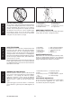
Do not start engine near fuelling spot E N G L I S H FUEL a) Use an appropriate type fuel container. b) Do not smoke or bring flame or sparks near fuel supplies. The fuel tank may be under pressure. Always loosen the fuel cap and wait for pressure to be equalized before removing the cap. d) Fill the fuel tank outdoors over bare ground and install the fuel cap securely. Do not pour fuel indoors. I T A L I A N O f) It is highly flammable. c) D E U T S C H e) Wipe any spilled fuel off the unit.
c) d) AREA AND EQUIPMENT INSPECTION Inspect the area before using the unit. Remove objects the unit could throw. Remember where there are obstructions to be avoided. e) Inspect the unit before using it. Perform only maintenance or adjustments for which the operator’s Manual gives instruction. Do not try to repair the unit without proper instruction. The unit should be serviced only by trained ECHO dealer servicemen with the proper tools.
Start on ground with cutting attachment in the clear GENERAL OPERATION E N G L I S H Do not run the engine indoors, or where there is poor ventilation. Engine fumes contain deadly poisonous carbon monoxide. Do not operate with a worn or damaged cutting attachment. Do not run engine at full throttle without a load. Do not hit rocks, stones, tree stumps, and other foreign objects with the cutting attachment. Lay the unit down on a clear area and set the controls for starting.
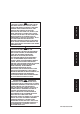
15 m Do not allow anyone to enter the operating DANGER ZONE with you. The danger zone is an area of 15 m in radius. Insist that persons in the RISK ZONE beyond the danger zone wear eye protection to protect them from thrown objects. If the unit must be used where there are unprotected people, operate at a low throttle speed to reduce the risk. Do not raise the cutting attachment above knee height. If raised higher, the cutting attachment will be more directly in line with your face.
E N G L I S H Stop the engine before leaving the machine, children are not allowed to use the machine , stop the machine between different working places. Sudden vibration? Shut down immediately! Shut down immediately if the unit starts to shake or vibrate. If you are approached, stop the engine and cutting attachment immediately. Keep your hands and body away from silencer to prevent heat injury while the engine is hot.
Keep feet and hands away until rotation stops. Do not operate one-handed When the unit is turned off, make sure the cutting attachment stops before the unit is set down. All maintenance and adjustments given in this manual should be performed by you or your ECHO servicing dealer on a timely basis. All required service or repair must be done only by ECHO servicing dealer. Never attempt to use an incomplete or one fitted with unauthorized modification.
E N G L I S H SCYTHING WEEDS. This is cutting by swinging the cutting attachment in a level arc. It can quickly clear areas of field grass and weeds. Scything should not be used to cut large, tough weeds or woody growths. WARNING DANGER ALWAYS STOP THE ENGINE WHEN A CUTTING ATTACHMENT JAM OCCURS. DO NOT ATTEMPT TO REMOVE AN OBJECT CAUSING A JAM IF THE ENGINE IS RUNNING. SEVERE INJURY CAN OCCUR IF A JAM IS REMOVED AND THE CUTTING ATTACHMENT SUDDENLY STARTS.
2 1 Anticlockwise rotation 1. Push 2. Pull Kickback REACTION FORCES WARNING PULL. The opposite of push. When object on left, the operator may feel the unit pull away. Although this pull type of cutting may cause sawdust to be thrown back at the operator, it is recommended for sawing off heavy brush because the cutting is smoother and more stable than when the unit pushes.
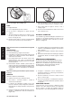
1 2 3 E N G L I S H D E U T S C H I T A L I A N O 1. Blade 2. Cup 3. Nut USE CORRECT BLADE WARNING • THE 3 CUTTER BLADE IS DESIGNED ESPECIALLY TO CUT WEEDS AND GRASS. TO AVOID INJURY DUE TO KICKBACK OR BLADE FRACTURE, DO NOT USE THE 3 CUTTER BLADE TO CUT BRUSH OR TREES. • USE ONLY CUTTING ATTACHMENTS RECOMMENDED BY KIORITZ CORPORATION. DANGER • SERIOUS INJURY MAY RESULT FROM THE IMPROPER USE OF BLADES. READ AND COMPLY WITH ALL SAFETY INSTRUCTIONS LISTED IN THIS MANUAL. 1. Messer 2. Auflagekappe 3.
• Always use the blade suited for the job. Inspect blades before use WARNING • Do not hit rocks, stones, tree stumps, and other foreign objects with the blade. DANGER • Do not cut into the ground with the blade. PIECES FROM A CRACKED METAL BLADE CAN FLY OFF DURING OPERATION. INSPECT METAL BLADES FOR CRACKS BEFORE EACH USE. DISCARD CRACKED BLADES NO MATTER HOW SMALL THE CRACK. CRACKED BLADES CAN BE THE RESULT OF MISUSE OR IMPROPER SHARPENING.
VIBRATION AND COLD E N G L I S H It is believed that a condition called Raynaud’s Phenomenon which affects the fingers of certain individuals may be brought about by exposure to vibration and cold. Exposure to vibration and cold may cause tingling and burning, followed by loss of colour and numbness in the fingers. The following precautions are strongly recommended because the minimum exposure which might trigger the ailment is unknown.
Painful or numb fingers? See your doctor immediatelty! REPETITIVE STRESS INJURIES To reduce the risk of RSI, do the following: It is believed that overusing the muscles and tendons of the fingers, hands, arms and shoulders may cause soreness, swelling, numbness, weakness and extreme pain to the areas just mentioned. Certain repetitive hand activities may put you at a high risk for developing a repetitive stress injury (RSI). • Avoid using your wrist in a bent, extended or twisted position.
DESCRIPTION BESCHREIBUNG DESCRIZIONE GB ENGLISH D DEUTSCH I ITALIANO 1 E N G L I S H 4 21 5 7 10 12 11 D E U T S C H 3 8 9 20 14 13 15 I T A L I A N O 2 6 16 17 19 18 RM-4000/4000SI/5000 22
DESCRIPTION GB 1 OPERATOR’S MANUAL Included with unit. Read before operation and keep for future reference to learn proper, safe operating techniques. 2 CUTTING ATTACHMENT 3 cutter blade for cutting grass, garden debris and weeds. 3 SHIELD Device to protect the operator from accidental contact with the cutting head and thrown objects. 4 ANGLE TRANSMISSION Having two gears to change the angle of rotating axis. 5 SHAFT TUBE Part of the unit that provides a casing for power transmission shaft.
BESCHREIBUNG D 1 E N G L I S H D E U T S C H BEDIENUNGSANLEITUNG Wird mit dem Gerät mitgeliefert. Vor Betrieb lesen und zum Nachschlagen sicher aufbewahren, damit Sie lernen, mit dem Gerät sicher und ordnungsgemäß umzugehen. 2 ARBEITSWARKZEUG 3-Zahnmesser, geeignet zum Schneiden von Gras, Sträuchem und Wildwuchs. 3 SCHUTZSCHILD Wird benötigt, um Bedienungspersonal und Passanten vor Steinschlag zu schützen. 4 WINKELGETRIEBE Ermöglicht es den Winkel der Rotationsachse zu wechsein.
I 1 DESCRIZIONE (Far riferimento a pag. 22) MANUALE DELL’OPERATORE. A corredo dell’attrezzo. Leggere prima dell’uso e conservare per futura consultazione al fine di imparare ad usare l’attrezzo correttamente e con sicurezza. 11 IMPUGNATURA POSTERIORE. Impugnatura posizionata verso la parte a zaino della macchina. 2 ACCESSORIO DI TAGLIO. Disco da 3 denti per il taglio dell’erba e di erbacce dei giardini. 13 CALOTTA DEL SILENZIATORE. Impedisce all’operatore di toccare lo scarico che scotta.
1 2 3 4 7 6 7 5 E N G L I S H ASSEMBLING 1. Power transmission shaft (F) 2. Holder 3. Power transmission shaft (R) 4. Spacer 5. Connector 6. Socket 7. Bolt FLEXIBLE SHAFT ASSEMBLY First stage of assembling is coupling of the power transmission shaft (F) and (R). • Insert connector into holder and tighten bolt securely using hexagonal wrench. • Loosen bolt with hexagonal wrench. • Insert the power transmission shaft (R) with the spacer into the socket gradually and fully.
5 6 3 1 4 8 1 7 2 3 2 1. Lock pin 2. Push 3. Power transmission shaft (R) 1. Joint 2. Inner cable 3. Holder Second stage is coupling of the power transmission shaft (R) and the engine. • As pushing in the lock pin fully, insert the other end of power transmission (R) to the driving shaft of the engine. 4. 5. 6. 7. 8. Lead (A) Lead (B) Throttle cable Cover (A) Cover (B) THROTTLE CABLE RETAINER ASS’Y This ass’y is designed to provide a simple connection and adjustment for the throttle cable.
1 2 2 1 4 3 5 3 E N G L I S H D E U T S C H I T A L I A N O 1. Cover (A) 2. Cover (B) 3. Throttole cable 4. Engine side 5. Shaft tube side 1. Clip 2. Flexible shaft assembly 3. Throttle cable • The length of inner cable can be adjusted for proper pulling by opening cover (B) and resetting flange of throttle cable into a suitable groove on the left or right.
5 1 2 1 2 6 3 3 4 1. Screw M5× 35 2. Front handle 3. Bracket 1. Front handle 2. Hanger 3. Strap 4. Nut 5. Hanger 6. Shaft tube LOOP HANDLE SHOULDER HARNESS • Assemble the front handle and bracket on the shaft tube loosely. • Suit the length of knapsack band to comfort. • As the strap is elastic and adjustable, it is preferable to connect the strap to the hangers located on the front handle and the left or right knapsack band to maintain a fatigueless and comfortable operation.
2 1 1 3 3 4 4 5 5 E N G L I S H 1. Bracket 2. Bolt M5× 25 3. Convex of fitting plate 6 2 4. Fitting plate 5. Notch of fitting plate 1. Blade retainer fixing slot 2. Blade retainer 3. Blade INSTALLATION OF BRACKET INSTALLING BLADE Fit bracket to mounting portion of angle transmission and fix the bracket by holding fitting plate pressed from beneath and tightening 4 bolts (M5× 25) lightly. Inspect blades before installation. Check for sharpness.
1 2 1 2 1. Blade 2. Locking tool 1. Socket wrench 2. Blade Insert locking tool into a hole located on the right side of angle transmission while forcing retainer spring to the left side. Insert locking tool further into blade retainer fixing slot to fix output shaft. Tighten the nut (turn anticlockwise) using a socket wrench. Never fasten while applying your weight. Otherwise the thread of nut could be broken. Replace nut and cup with new ones no matter how small the wear is.
E N G L I S H FUEL FUEL - Do not mix directly in engine fuel tank. • Fuel is a mixture of regular grade petrol and an aircooled 2-stroke engine oil of reputable brand name. Minimum 89 Octane unleaded petrol is recommended. Do not use fuel containing methyl alcohol or more than 10 % of ethyl alcohol. - Avoid spilling petrol or oil. Spilled fuel should always be wiped up. - Handle petrol with care, it is highly inflammable. - Always store fuel in approved container.
1 2 1. Fuel tank 2. Shoulder level HANDLING FUEL WARNING • Always remove the fuel cap slowly to relieve any pressure buildup in the tank. DANGER AFTER REFUELLING TIGHTEN FUEL CAP FIRMLY AND CHECK FOR LEAKAGE. IN CASE OF FUEL LEAKAGE REPAIR BEFORE STARTING OPERATION SINCE THERE IS A DANGER OF FIRE. • Never refuel the engine when it is hot or running. • Always use an approved, safe fuel container. E N G L I S H • It is not permitted to fill fuel above the shoulder level of fuel tank.
1 START 5 3 3 4 2 2 E N G L I S H OPERATION 1. Ignition switch 2. Throttle trigger 3. Throttle trigger lockout 1. Purge bulb 2. Choke lever WARNING • Place ignition switch in “START” position. DANGER • WHEN ENGINE IS STARTED, CONFIRM IF THERE IS NOT ANY ABNORMAL VIBRATION OR SOUND. IF THERE IS ABNORMAL VIBRATION OR SOUND, ASK YOUR DEALER TO REPAIR. I T A L I A N O 3. Start (CLOSE) 4. Run (OPEN) 5.
5 3 1 4 2 1. Purge bulb 2. Choke lever 1 3. Start (CLOSE) 4. Run (OPEN) 5. Starter handle 1. Decompression device (RM-4000, RM-5000) STARTING WARM ENGINE NOTE • Place ignition switch in “START” position. • Check unit for loose nuts, bolts and screws before starting. • Move choke lever to OPEN position. • Press the decompression device. (RM-4000, RM-5000) • Always clear work area of debris before starting operation. • If tank is not empty, pull starter handle.
1 1 2 E N G L I S H 1. Ignition switch 1. Spark plug wire 2. Spark plug STOPPING ENGINE Always disconnect the spark plug wire from the spark plug to ensure the engine cannot be started before you work on the unit or leave it unattended. • Release throttle trigger and allow engine to idle. • Place ignition switch in “STOP” position. WARNING DANGER IF ENGINE DOES NOT STOP, CLOSE CHOKE TO STALL ENGINE. HAVE YOUR ECHO DEALER INSPECT AND REPAIR IGNITION SWITCH BEFORE USING THE UNIT. D E U T S C H 1.
1 2 3 3. OPERATING THE UNIT Spectators and fellow workers must be warned and children and animals prevented from coming near than 15 m while the grasstrimmer/brushcutter is in use. 4. Rread carefully the “rules for safe operation”. Put on the knapsack band ass’y as follows: 4 For even load on both sides of shoulder, joggle the unit on the shoulder a couple of times.
E N G L I S H Hold the front handle (loop handle) and rear handle both hands. • The blade rotates anticlockwise, so it is necessary to cut the object from the right to the left. • The manner of walking is as follows: - Step the right foot forward firstly and secure your footing. • Do not cut into the ground. • Do not run the unit unloaded at full throttle to avoid damage to the engine. - And then follow the left foot to the behind of the right foot.
1 2 2 1 MAINTENANCE AND CARE 1. Air filter 2. Air cleaner cover 1. Fuel filter 2. Fuel line • If you have any questions or troubles, please contact ECHO dealer. REPLACING FUEL FILTER • Use a piece of steel wire or the like to pick up fuel filter through fuel tank opening. CLEANING AIR FILTER • Close choke. Loosen screws and remove air cleaner cover. • Pull old filter from fuel line. E N G L I S H • Install new fuel filter. • Remove air filter (air filter is located inside air cleaner cover).
T E N G L I S H T : Idle speed adjuster CAUTION CARBURETTOR ADJUSTMENT When starting, idle speed adjuster should be adjusted not to rotate the cutting attachment. When there is some trouble with the carburettor, contact your dealer. WARNING DANGER WHEN CARBURETTOR ADJUSTMENT IS COMPLETED, CUTTING ATTACHMENT SHOULD NOT MOVE AT IDLE, OTHERWISE SERIOUS PERSONAL INJURY MAY RESULT.
1 2 • Air intakes are blocked, preventing cooling air from reaching the cylinder, 1. Cylinder fins 2. Air intake or COOLING SYSTEM MAINTENANCE • Dust and grass build up on the out side of the cylinder. This build-up insulates the engine and prevents the heat from leaving. IMPORTANT To maintain proper engine operating temperature, cooling air must pass freely through the cylinder fin area. This flow of air carries combustion heat away from the engine.
3 CHECK FUEL SYSTEM E N G L I S H • Check before every use. • After refuelling make sure fuel does not leak or exude from around fuel pipe, fuel grommet or fuel tank cap. • In case of fuel leakage or exudation there is a danger of fire. Stop using the machine immediately and request your dealer to inspect or replace. 2 1 1. Heat shield 2. Silencer 3. Silencer cover CLEANING SILENCER AND EXHAUST PORT • Remove silencer cover. • Remove silencer and heat shield. • Place piston at top dead centre.
1 2 0.6 - 0.7 mm 1. Angle transmission 2. Plug (Bolt) CHECK SPARK PLUG • Check plug gap. Correct gap is 0.6 to 0.7 mm. • Inspect electrode for wear. ANGLE TRANSMISSION • Inspect insulator for oil or other deposits. • Remove plug from angle transmission. • Replace plug if needed and tighten to 15 - 17 N • m (150 to 170 kgf• cm). • Add grease, if necessary, using low pressure pump. E N G L I S H NOTE Use good quality lithium multi grease. DO NOT overfill housing. • Reinstall plug. 1.
1 E N G L I S H 2 1. Flexible shaft 2. Power transmission shaft • The major points necessary for disassembling and reassembling are as follows: - As pushing in the lock pin of the engine fully, draw out the flexible shaft assembly from the engine. FLEXIBLE SHAFT • All the surface of the power transmission shaft (R) should always be properly greased. - Unfasten the coupling of the flexible shaft assembly at the grip end, draw out the flexible shaft assembly from the rear handle assembly.
30° CHECKING THE BLADE • Use only the blade designated for this model by the manufacturer. • When the cutting blade becomes dull due to wear reverse it for further use. • When a crack is noticed on the blade, do not use it but replace with a new one. • When chip or bend occurs on the blade, vibration will increase. Replace with a new one. • Ensure that the blade is correctly fitted in accordance with the instructions.
SERVICING GUIDE E N G L I S H AREA Air Filter Fuel Filter Spark Plug Carburettor Cooling System Silencer Angle Transmission Flexible Shaft Starter Cut off Knife Fuel System Screws, Bolts and Nuts MAINTENANCE Clean/Replace Inspect/Clean/Replace Inspect/Clean/Adjust/Replace Adjust/Replace and adjust Inspect/Clean Inspect/Tighten/Clean Grease Grease Inspect Inspect/Clean Inspect Inspect, Tighten/Replace PAGE 39 39 43 40 41 42 43 44 (47) 42 - BEFORE USE • • MONTHLY • • • • •** •* • • • • IMPORTANT Time
TROUBLE SHOOTING GB Trouble Engine - starts hard - does not start Engine cranks Fuel at carburettor No fuel at carburettor • Fuel filter clogged • Fuel line clogged • Carburettor • Clean or replace • Clean • Ask your ECHO dealer Fuel at cylinder No fuel at cylinder • Carburettor • Ask your ECHO dealer Cause Remedy Silencer wet with • Fuel mixture is too rich fuel Open choke Clean/replace air filter Adjust carburettor Ask your ECHO dealer Spark at end of plug wire No spark at end of plug wir
BEHEBUNG VON BETRIEBSSTÖRUNGEN D Problem - springt nicht leicht an - springt gar nicht an Motor lässt sich starten Kraftstoff am Vergaser Kein Kraftstoff am Vergaser • Kraftstoffilterelement verstopft • Reinigen oder austauschen • Kraftstoffleitung verstopft • Reinigen • Vergaser • ECHO Vertragswerkstatt konsultieren Kraftstoff am Zylinder Kein Kraftstoff am Zylinder • Vergaser • ECHO Vertragswerkstatt konsultieren Schalldämpfer mit Kraftstoff benetzt • Kraftstoffgemisch zu fett • Choke öffnen
PROBLEMI TECNICI I Guasto Motore - avviamento difficile - non si avvia Motore in moto Carburante al carburatore Rimedio • Filtro carburante ostruito • Linea alimentazione carburante otturata • Carburatore • Pulire o sostituire • Pulire Niente carburante al cilindro • Carburatore • Rivolgersi al proprio rivenditore ECHO.
3 1 2 4 3 5 1 2 INSTALLING NYLON LINE CUTTER (OPTION) E N G L I S H 1. Blade retainer fixing slot 2. Blade retainer 3. Nylon line cutting attachment 4. Cut off knife 1. Bracket 2. Shield 5. Screw 5× 12 3. Screw M5× 18 There are two types of shields: namely one used exclusively for Nylon line and another one used exclusively for steel blade. When Nylon line is used, use the shield for Nylon line. When steel blade is used, use the shield for steel blade.
2 1 2 1 3 1. Locking tool 2. Nylon line cutting attachment 1. Tap knob 2. Hit knob against the ground surface lightly 3. Nylon line comes out CAUTION ADJUSTING NYLON LINE Fasten output shaft using locking tool securely in order to avoid the possibility of output shaft rotating when mounting nylon line cutting attachment. Thread cutting attachment onto shaft (anticlockwise) until it is tight. Remove locking tool. NYLON LINE CUTTING ATTACHMENT Type: Thread: Z5 Left-hand thread M10 × 1.25 pitch 1.
(2) 3 1 (3) (1) E N G L I S H • Cut off knife on the guard adjusts cutting swath to 40 cm automatically by cutting nylon lines evenly when attachment starts rotating. • When operating with less than maximum cutting swath (40 cm), cut two nylon lines in equal lengths. CAUTION Use only flexible, non-metallic line recommended by KIORITZ CORPORATION.
(4) (5) 12 cm (6) 5 (7) 4 3 6 1 1. 2. 3. 4. 5. 6. 2 Bent portion Notch Nylon line Intermediate separator Winding direction for the line If wound unfirmly, the line loosens. Wind firmly into respective groove. (6) When the line is wound to the end hook both line ends into respective notch of spool for retaining tentatively the line while leaving line ends approximately 10 cm beyond notch. (7) Align notches of spool for the line with grooves of eyelets and fit spool into cover.
(8) (9) (C) (D) (A) (B) E N G L I S H D E U T S C H I T A L I A N O (8) Pull out the line from cover. (A) Remove the line from “respective notch of spool”, and (B) pass it through “groove of respective eyelet”. WARNING (9) Fit cover and housing together. (C) Align “eyelets” of cover with “recesses” of housing, and (D) press pawls of housing into respective window of cover until the pawls are firmly fitted into the windows. (8) Faden aus den Deckel ziehen.
(1) (3) (4) (5) CHECKING THE NYLON LINE CUTTING ATTACHMENT (1) Make sure each periphery of the 2 retaining pawls of housing spreads almost fully up to the outer periphery of the respective cover window. (4) Inspect cover and tap knob for wear. When slot appears on bottom of the tap knob or when slot apperars on cover bottom close to outlet for nylon line, replace them with new parts without fail. (2) Check mount of cutting head on trimmer and tighten if it is loose.
E N G L I S H OPERATING NYLON LINE CUTTING ATTACHMENT TRIMMING The nylon line will allow you to trim along walls and fence lines. Always try to trim from right to left, walking behind the unit and parallel to the wall or fence, thus deflecting debris away from the operator. EDGING The nylon line is intended only to cut grass and should not be used to cut a normal edging trench along stone or concrete driveways etc.
SWEEPING E N G L I S H Sweeping grass and other debris from a hard surface can be done very quickly. KEHREN D E U T S C H Gras und andere Fremdkörper lassen sich von festem Untergrund leicht wegfegen. RIFINITURA I T A L I A N O In breve tempo spazza erba ed altri rifiuti da superfici dure.
1 E N G L I S H STORAGE 1. Ignition switch LONG TERM STORAGE (Over 30 Days) Do not store your unit for a prolonged period of time (30 days or longer) without performing protective storage maintenance which includes the following: 1. Store unit in a dry, dust free place, out of the reach of children and other unauthorized persons. WARNING 2. Place ignition switch in “STOP” position. 3. Remove accumulation of grease, oil, dirt and debris from exterior of unit. 4.
6. 7. Drain the fuel tank completely and pull the recoil starter handle several times to remove fuel from the carburettor. NOTE • For future reference, you should keep this operator’s manual. • If this operator’s manual has become illegible through impairment or is lost, please purchase a new one from your ECHO dealer.
GB SPECIFICATIONS RM-4000 (SI) E N G L I S H RM-5000 Mass : unit without cutting attachment, empty tank unit with specified cutting attachment, empty tank unit with specified cutting attachment, full tank kg kg kg Volume : fuel tank L 1.3 mm mm mm 255 2.0 3 25.4 r/min 10,000 Cutting attachment : specified blade diameter specified blade thickness number of cutting teeth blade centre hole diameter blade rotational speed at maximum allowable engine speed 11.1 (11.4) 11.5 (11.8) 12.5 (12.
D TECHNISCHE DATEN Maße : Gerät ohne Schneidvorrichtung, leerer Tank Gerät mit spezifizierter Schneidvorrichtung, leerer Tank Gerät mit spezifizierter Schneidvorrichtung, voller Tank Fassungsvermögen : Kraftstofftank Mähausrüstung : spezifizierter Klingendurchmesser spezifizierte Klingenstärke Anzahl der Schneidzähne Durchmesser der zentralen Aussparung in der Klinge Klingendrehzahl bei maximaler zulässiger Motordrehzahl Untersetzungsverhältnis : Untersetzungsverhältnis und Schmierung Drehrichtung der Ant
I CARATTERISTICHE TECNICHE RM-4000 (SI) Massa : attrezzo senza apparato di taglio, serbatoio vuoto attrezzo con apparato di taglio specificato, serbatoio vuoto attrezzo con apparato di taglio specificato, serbatoio pieno Volume : serbatoio del carburante E N G L I S H Apparato di taglio : diametro lama specificata spessore lama specificata numero denti di taglio diametro foro centrale lama velocità di rotazione lama al massimo regime cosentito kg 11,1 (11,4) 11,1 kg 11,5 (11,8) 11,5 kg 12,5 (12,8
DECLARATION “CE” OF CONFORMITY DICHIARAZIONE DI CONFORMITÀ “CE” The undersigned manufacturer: II produttore sottoscritto: KIORITZ CORPORATION 7-2 SUEHIROCHO 1-CHOME OHME ; TOKYO 198-8711 JAPAN KIORITZ CORPORATION 7-2 SUEHIROCHO 1-CHOME OHME ; TOKYO 198-8711 GIAPPONE declares that the hereunder specified new unit: dichiara che la nuova macchina sottocitata: PORTABLE BRUSHCUTTER DECESPUGLIATORE PORTATILE A SCOPPIO Brand : ECHO Type : RM-4000 RM-4000SI RM-5000 MARCHIO : ECHO TIPO : RM-4000 RM-4000SI
E N G L I S H D E U T S C H I T A L I A N O RM-4000/4000SI/5000 EG-Konformitätserklärung Wir als Hersteller: KIORITZ CORPORATION 7-2 SUEHIROCHO 1-CHOME OHME ; TOKYO 198-8711 JAPAN erklären, daß das nachfolgende neue Motorgerät: MOTORSENSE / FREISCHNEIDEGERÄT Fabrikat : ECHO Typ : RM-4000 RM-4000SI RM-5000 64 mit den Erfordernissen der EG-Maschinenrichtlinie 98/37/EC (1998) u. der Richtlinie 89/336/EWG übereinstimmt.
Gewährleistungs- und Garantiebestimmungen für ECHO- Motorgeräte 7. Ausschluß von der Gewährleistung 7a. Von der Garantieleistung ausgenommen sind Schäden die infolge unsachgemäßer Bedienung und unsachgemäßer Reparatur durch Dritte, wegen mangelhafter Pflege und Wartung oder wegen falschem Gebrauch entstanden sind. Des weiteren sind Beschädigungen durch Fremdeinwirkungen und/oder Fremdkörper sowie Versand- und Transportkosten von der Garantie ausgeschlossen.
MEMORANDUM E N G L I S H D E U T S C H I T A L I A N O RM-4000/4000SI/5000 66
MEMORANDUM 67 RM-4000/4000SI/5000
7-2 SUEHIROCHO 1-CHOME, OHME, TOKYO 198-8711, JAPAN PHONE: 81-428-32-6118. FAX: 81-428-32-6145.