Grass Trimmer/Brush Cutter Operator's Manual MODELS, Type 1E SRM - 2100, 2110 Serial Number 982333 & Up WARNING DANGER Read rules for safe operation and instructions carefully. ECHO provides an Operator's Manual and a Safety Manual. Both must be read and understood for proper and safe operation.
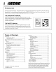
GRASS TRIMMER/BRUSH CUTTER OPERATOR'S MANUAL 3 MANUAL SAFETY SYMBOLS AND IMPORTANT INFORMATION Throughout this manual and on the product itself, you will find safety alerts and helpful, information messages preceded by symbols or key words. The following is an explanation of those symbols and key words and what they mean to you. This symbol accompanied by the words WARNING and DANGER calls attention to an act or condition that can lead to serious personal injury to operator and bystanders.
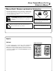
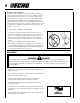
Shaft Decal P/N 89016844830 WARNING DANGER • This unit can be dangerous and cause serious injury if improperly used. To reduce injury risk to operator, helpers and bystanders, read and understand the Operator's and Safety manuals. • Blindness can occur from objects that are thrown or ricocheted even with shield in place. Operators, helpers and bystanders must wear ANSI Z87.1 approved eye protection. • Always wear hearing protection when operating unit.
GRASS TRIMMER/BRUSH CUTTER OPERATOR'S MANUAL 5 SAFETY INSTRUCTIONS PERSONAL CONDITION AND SAFETY EQUIPMENT WARNING DANGER Trimmer/Brush Cutter users risk injury to themselves and others if the trimmer/brush cutter is used improperly and or safety precautions are not followed. Proper clothing and safety gear must be worn when operating a trimmer.
Repetitive Stress Injuries It is believed that overusing the muscles and tendons of the fingers, hands, arms and shoulders may cause soreness, swelling, numbness, weakness and extreme pain in those areas. Certain repetitive hand activities may put you at a high risk for developing a Repetitive Stress Injury (RSI). An extreme RSI condition is Carpal Tunnel Syndrome (CTS), which could occur when your wrist swells and squeezes a vital nerve that runs through the area.
GRASS TRIMMER/BRUSH CUTTER OPERATOR'S MANUAL 7 SAFE OPERATION WARNING DANGER Do not operate this product indoors or in inadequately ventilated areas. Engine exhaust contains poisonous emissions and can cause serious injury or death. • Provide all operators of this equipment with the Operator's Manual and instructions for safe operation.
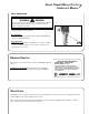
CONTENTS CONTENTS LIST MODELS ITEMS 1 - POWER HEAD 1 - DRIVE SHAFT ASSEMBLY 1 - PLASTIC BAG (CO-PACK) - 1, OPERATOR'S MANUAL - 1, SAFETY MANUAL - 1, WARRANTY REGISTRATION CARD - 1, LIMITED WARRANTY STATEMENT - 1, PLASTIC SHIELD - 1, PLASTIC SHIELD HARDWARE --1, SHIELD PLATE --3, 5MM X 15MM SCREWS (SHIELD MTG.) - 1, ASSEMBLY TOOLS --1, 8MM X 10MM WRENCH --1, SCRENCH --1, LOCKING TOOL - 1, NYLON TRIMMER HEAD - 1, SAFETY GLASSES - 1, 2-STROKE OIL SAMPLE, 2.6 OZ.
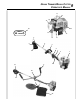
GRASS TRIMMER/BRUSH CUTTER OPERATOR'S MANUAL 9 11 12 18 19 13 25 SAFETY VIDEO 17 14 16 7 15 6 8 5 4 3 9 2 4 21 10 20 22 23 24 1
1. POWER HEAD - Includes the Engine, Clutch, Fuel System, Ignition System and Recoil Starter. 2. GRIP - Rear (right hand) handle. 3. THROTTLE TRIGGER LOCKOUT - This lever must be held down during starting. Operation of the throttle trigger is prevented unless throttle trigger lockout lever is depressed. 4. STOP SWITCH - "SLIDE SWITCH" mounted on top of the Throttle Trigger Housing. Move switch FORWARD to RUN, BACK to STOP. 5.
GRASS TRIMMER/BRUSH CUTTER OPERATOR'S MANUAL SPECIFICATIONS MOD EL SR M-2100 SR M-2110 Length 1500 mm (59 i n.) Wi dth 330 mm (13.0 i n.) 600 mm (23.6 i n.) Hei ght 300 mm (11.8 i n.) 360 mm (14.2 i n.) 5.2 kg (11.4 lb.) 5.8 kg (12.7 lb.) Wei ght (dry) w/cutter head Engi ne Type Ai r cooled, two-stroke, si ngle cyli nder gasoli ne engi ne Bore 32.2 mm (1.268 i n.) Stroke 26.0 mm (1.02 i n.) D i splacement 21.2 cc (1.29 cu. i n.
ASSEMBLY WARNING DANGER Use only ECHO approved attachments for these models. Serious injury may result from the use of non approved attachment combinations. Read and comply with all safety instructions listed in this manual and attachment manual. ECHO, INC. will not be responsible for the failure of cutting devices, attachments or accessories which have not been tested and approved by ECHO for use with these units. PLASTIC SHIELD INSTALLATION (for Nylon Line Operation) Tools Required: Screwdriver.
GRASS TRIMMER/BRUSH CUTTER OPERATOR'S MANUAL BLADE INSTALLATION All Models. IMPORTANT If non-standard monofilament head, METAL/PLASTIC blade or cultivator etc. is used, THE CARBURETOR MUST BE RE-SET or serious engine damage may occur. See "Carburetor Adjustment" page 27 and "Specifications" page 11 of this manual. WARNING DANGER You must install a U-Handle Kit and Blade Conversion kit before operating this unit using metal blades, otherwise serious injury may result.
Install Harness Clamp NOTE Some models require installation of Harness Clamp. If your unit does not have a clamp, follow these directions. Tools Required: Screwdriver, 8mm x 10mm Open End Wrench. Parts Required: Clamp, 4mm x 18mm Hexagon Head, Bolt, Link. 6. Remove shield and gear housing as an assembly. a. Loosen two (2) screws that clamp the gear housing to the drive shaft housing. b. Remove locating screw found at the top of the gear housing.
GRASS TRIMMER/BRUSH CUTTER OPERATOR'S MANUAL THROTTLE LINKAGE AND IGNITION LEADS Tools Required: 8mm x 10mm open end wrench (all models), 3mm Allen Wrench. 1. Close choke and remove air filter cover. 2. Loosen nut (A) and place threaded end of throttle linkage in bracket slot. Finger tighten nut (A). 3. Place inner cable in slot of carburetor swivel (B) and tighten nut (A). 4. Check throttle for freedom of movement and make sure it returns to idle position.
U-HANDLE INSTALLATION Tools Required: 8mm x 10mm Open End Wrench, Slotted Screwdriver, (3mm Hex Wrench SRM-2100 only.) Parts Required: U-Handle Kit. (SRM-2100) P/N 35130454130 NOTE On model SRM-2110 use Steps 1, 10, 11, and 13 - 17 only. 1. Close choke and remove air filter cover. 2. Disconnect ignition stop leads (C). 3. Remove inner throttle linkage from carburetor swivel (B). 4. Loosen nut (A) and remove throttle linkage from bracket. 5.
GRASS TRIMMER/BRUSH CUTTER OPERATOR'S MANUAL 11. Secure throttle linkage and leads to drive shaft with cable clips supplied. 12. Install power head and align gear box, power head and U-handles. Tighten all screws. 13. Place throttle linkage in slot in bracket with one nut (A) and washer on each side of bracket. Finger tighten both nuts (A). 14. Attach inner throttle cable to swivel (B). Check throttle for freedom of movement and that wide open throttle / low idle extremes are adjusted properly.
PRE - OPERATION OPERATION WITH BLADES Preparing the Trimmer/Brush Cutter for Blade Use WARNING DANGER Blade use DEMANDS specific Brush Cutter configuration. Operation without specified shield and harness can result in serious personal injury. Plastic and Nylon Blades Require "Blade Conversion Kit," P/N 99922200415 (metal shield, barrier bar, and shoulder harness). Steel/Metal Blades Require "Blade Conversion Kit" PLUS a "U-Handle Kit.
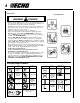
GRASS TRIMMER/BRUSH CUTTER OPERATOR'S MANUAL Plastic/Nylon Blades may be used where ever the nylon line head is used. DO NOT use this blade for heavy weeds or brush! 8 Tooth Weed/Grass Blade P/N 69600120331 is designed for grass, garden debris and thick weeds. DO NOT use this blade for brush or heavy woody growth, 3/4" in. (19 mm) diameter or larger. Brush/Clearing Blade P/N 69500120331 is designed for cutting brush and woody growth up to 76 mm (3" in.) diameter.
FUEL Fuel Requirements Gasoline - Use 89 Octane [R +2 M ] gasoline or gasohol known to be good quality. Gasohol may contain up to 10% Ethyl (grain) alcohol or 15% MTBE (methyl tertiary-butyl ether). Gasohol containing methyl (wood) alcohol is NOT approved. Two Stroke Oil - A two-stroke engine oil meeting ISO-L-EGD Standard (ISO/CD 13738), must be used. Echo brand Premium 50:1 oil meets this standard.
GRASS TRIMMER/BRUSH CUTTER OPERATOR'S MANUAL OPERATION STARTING COLD ENGINE WARNING DANGER The cutting attachment should not move at idle. If cutting attachment moves, readjust carburetor according to "Carburetor Adjustment" instructions in this manual or see your ECHO Dealer, otherwise serious personal injury may result. A 1 . Stop Switch - Start/Run. Move stop switch button (A) forward away from the STOP position. 2. Choke - Cold Start. Move choke (B) to “Cold Start” Position. 3. Primer Bulb -Purge.
STARTING WARM ENGINE The starting procedure is the same as Cold Start except DO NOT close the choke. WARNING DANGER The cutting attachment should not move at idle. If cutting attachment moves, readjust carburetor according to "Carburetor Adjustment" instructions in this manual or see your ECHO Dealer, otherwise serious personal injury may result. A 1. Stop Switch - Start/Run. Move Stop Switch button (A) forward away from the STOP position. 2. Start - Pull Rope.
GRASS TRIMMER/BRUSH CUTTER OPERATOR'S MANUAL 23 MAINTENANCE Your ECHO unit is designed to provide many hours of trouble-free service. Regular scheduled maintenance will help your unit achieve that goal. If you are unsure or are not equipped with the necessary tools, you may want to take your unit to an ECHO Service Dealer for maintenance. To help you decide whether you want to DO-IT-YOURSELF or have the ECHO Dealer do it, each maintenance task has been graded.
AIR FILTER Level 1. Tools required: Cleaning Brush Parts required: 90008 REPOWER AIR & FUEL FILTER KIT. 1. Close choke (Cold Start Position). This prevents dirt from entering the carburetor throat when the air filter is removed. Brush accumulated dirt from the air cleaner area. 2. Remove the air cleaner cover. Clean and inspect the element for damage. If element is fuel soaked and very dirty, replace. 3.
GRASS TRIMMER/BRUSH CUTTER OPERATOR'S MANUAL SPARK PLUG Level 2. Tools required: Scrench (combination socket wrench and screw driver supplied with unit), Feeler gauge (preferably a wire gauge), Soft metal brush Parts Required: Spark Plug NGK BPM-7A 1. Remove spark plug and check for fouling, worn and rounded center electrode. 2. Clean the plug or replace with a new one. DO NOT sand blast to clean. Remaining sand will damage engine. 3. Adjust spark plug gap by bending outer electrode. 4.
2. Remove the four screws that retain the engine cover (A). Two at the top of the starter, two on either side of the front. Lift the cover from the engine and lay to the front of the trimmer. NOTE The throttle linkage remains assembled to the cover and the spark plug lead and grommet remain installed. 3. Use the wooden stick or brush to remove dirt form cylinder fins. 4. Remove grass and leaves from the grid between the recoil starter and fuel tank. 5. Assemble components in reverse order.
GRASS TRIMMER/BRUSH CUTTER OPERATOR'S MANUAL CARBURETOR ADJUSTMENT Emission Models Level 2. Tools required: Slotted Screwdriver w/2 mm blade width, Tachometer (ECHO P/N 99051130017) Parts required: None. NOTE Every unit is run at the factory and the carburetor is set in compliance with EPA Phase 1 and California Emission Regulations. In addition, the carburetor is equipped with HI and LO needle adjustment limiters that prevent settings outside acceptable limits. 1.
LUBRICATION Level 1. Tools required: 8 mm Open End Wrench, Cross Head Screwdriver, Clean rag Parts Required: ECHO® LUBETM 8 oz. (P/N 91014) or Lithium Base Grease. Gear Housing 1. Clean all loose debris from gear box. 2. Remove plug (A) and check level of grease. 3. Add grease if necessary, DO NOT over fill. A Drive Shaft 1. Loosen two (2) screws (B) and remove center locating screw (C). Pull gear box and shield from drive shaft housing. 2.
GRASS TRIMMER/BRUSH CUTTER OPERATOR'S MANUAL 1. Shut engine off. Lay unit on the ground with head assembly up. B 2. Hold drum (A) and turn spool (B) CW (clockwise) until it stops. Pull spool from drum. DO NOT push in on spool when turning. 3. Use one piece of new nylon line (C) 6m (20 ft.) long and thread through the molded loop (D) on the spool. Pull line tight and adjust so one end is 15 cm (6 in.) longer than the other. 4. Hold the spool, opening toward you.
SHARPENING METAL BLADES Three styles of metal blades are approved for use on the ECHO Brush Cutter. The 8-tooth blade can be sharpened during normal maintenance. The clearing blade and 80 tooth blade require professional service. Before sharpening, CLOSELY inspect blade for cracks (look at the bottom of each tooth and the center mounting hole closely), missing teeth and bending. If ANY of these problems are discovered, replace the blade.
GRASS TRIMMER/BRUSH CUTTER OPERATOR'S MANUAL 31 TROUBLESHOOTING ENGINE PROBLEM TROUBLESHOOTING CHART Problem C h eck Status No fuel at carburetor Clean or replace Clean or replace See your Echo dealer Carburetor See your Echo dealer Fuel Mixture too rich Open choke Clean/replace air filter Adjust carburetor See your Echo dealer No spark Stop switch off Electrical problem Interlock switch Turn switch to ON See your Echo dealer See your Echo dealer No spark Spark gap incorrect Covered with carbo
STORAGE Long Term Storage (over 30 days) WARNING DANGER During operation the muffler or catalytic muffler and surrounding cover become hot. Always keep exhaust area clear of flammable debris during transportation or when storing, otherwise serious property damage or personal injury may result . Do not store your unit for a prolonged period of time (30 days or longer) without performing protective storage maintenance which includes the following: 1.
GRASS TRIMMER/BRUSH CUTTER OPERATOR'S MANUAL NOTES 33
NOTES
GRASS TRIMMER/BRUSH CUTTER OPERATOR'S MANUAL NOTES 35
SERVICING INFORMATION PARTS Genuine ECHO Parts and ECHO Re Power Parts and Assemblies for your ECHO products are available only from an Authorized ECHO Dealer. When you do need to buy parts always have the Model Number, Type number and Serial Number of the unit with you. You can find all three numbers on the engine housing. For future reference, write them in the space provided below. Model No. ____________ Type No. ____________ SN. __________ DEALER? CALL 1-800-432-ECHO OR www.echo-usa.
DESCRIPTION Page 7 EMISSION CONTROL IMPORTANT ENGINE INFORMATION ENGINE FAMILY : 2EHXS.0214RA DISPLACEMENT : 21.2cc EMISSION COMPLIANCE PERIOD : 300 HRS. THIS ENGINE MEETS U.S. EPA PHASE 2 EMISSION REGULATIONS FOR SMALL NONROAD ENGINES. REFER TO OWNER'S MANUAL FOR MAINTENANCE SPECIFICATIONS AND ADJUSTMENTS.