GB ENGLISH OPERATOR’S MANUAL GRASS TRIMMER/ BRUSHCUTTER SRM-2305 WARNING DANGER READ INSTRUCTIONS CAREFULLY AND FOLLOW RULES FOR SAFE OPERATION. FAILURE TO DO SO COULD RESULT IN SERIOUS INJURY.
INTRODUCTION ECHO Grass Trimmers/Brushcutters are lightweight, high-performance, petrol engined units designed for weed control, grass trimming and brush cutting in areas difficult to control by any other means. This Manual provides the information necessary for assembly, operation and maintenance. You must read this Manual to understand the safe and effective operation of your ECHO product. CONTENTS Introduction ................................................................ 2 Decals and symbols .......
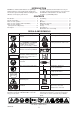
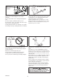
Operator’s manual Do not permit operation without proper training and protective equipment. RULES FOR SAFE OPERATION Read the Operator’s Manual carefully. Be thoroughly familiar with the controls and proper use of the unit. TRAINING WARNING DANGER Know how to stop the unit and shut off the engine. GRASS TRIMMERS AND BRUSHCUTTERS CAN THROW SMALL GRAVEL, STONE, GLASS, METAL OR PLASTIC OBJECTS AS WELL AS THE MATERIAL BEING CUT. READ THESE “RULES FOR SAFE OPERATION” WITH CARE.
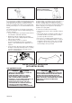
Balance tool for a level plane of cutting head rotation Harness quickrelease pin WARNING Ground level PREPARATION DANGER Use a shoulder harness when provided or when recommended in this manual. Adjust both harness and the suspension point on the unit so the unit hangs with the cutting attachment a few centimetres above ground level. The cutting attachment and shield should be level in all directions. Harness the unit on the right side as shown.
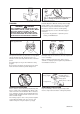
Do not start engine near fuelling spot FUEL PHYSICAL CONDITION It is highly flammable. You should be in good mental and physical health. Do not operate if you are under the influence of alcohol or any medication or substance which could affect your vision, dexterity or judgement. a) Use an appropriate type of fuel container. b) Do not smoke or bring flame or sparks near to fuel supplies. c) The fuel tank may be under pressure.
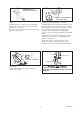
Start on ground with cutting attachment in the clear Do not run the engine indoors, or where there is poor ventilation. GENERAL OPERATION Engine fumes contain deadly poisonous carbon monoxide. Lay the unit down on a clear area and set the controls for starting. Be sure the cutting attachment cannot contact the ground or any obstruction. Do not operate with a worn or damaged cutting attachment. Hold the unit firmly down so you will not lose control during starting.
Sudden vibration? Shut down immediately! Keep feet and hands away until rotation stops. Shut down immediately if the unit starts to shake or vibrate. When the unit is turned off, make sure the cutting attachment stops before the unit is set down. A sudden vibration is a sign there may be dangerous trouble, such as a broken flywheel, clutch or cutting attachment, or loose parts. A cutting attachment can injure while it continues to spin after the engine is shut off or throttle control is released.
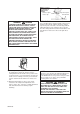
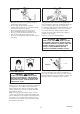
Painful or numb fingers? See your doctor immediatelty! VIBRATION AND COLD REPETITIVE STRESS INJURIES It is believed that a condition called Raynaud’s Phenomenon which affects the fingers of certain individuals may be brought about by exposure to vibration and cold. Exposure to vibration and cold may cause tingling and burning, followed by loss of colour and numbness in the fingers.
Wires can catch and flap around • Always use the blade suited for the job. • Do not hit rocks, stones, tree stumps, and other foreign objects with the blade. • Do not cut into the ground with the blade. • If blade strikes an obstruction, stop engine immediately and inspect blade for damage. • Do not operate with a dull, bent, fractured or discoloured blade and worn or damaged nut. • Do not run engine at full throttle without a load. • Remove all foreign objects from work area.
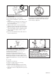
Debris Knife side raised Angle to ground Angle to wall RULES FOR SAFE OPERATION (WITH NYLON LINE CUTTING HEAD) The basic cutting actions pictured are: Trimming, scything, scalping and lawn edging. These actions are as follows: SCYTHING: This is the cutting or mowing of large grassy areas by sweeping or swinging the trimmer in a level arc. Use a smooth, easy motion. Do not try to hack or chop down the grass. Tilt the line head or line disc to direct the debris away from you on the scything stroke.
Line pushed into wire fencing will snap off. Do not trim near cars or pedestrians. WARNING Do not push the line into tough weeds, trees, or wire fences. Pushing the line into chicken wire, chain link fencing or thick brush can result in snapped-off line ends being hurled back at the operator. The proper way is to cut right up to a barrier, such as any of those mentioned, but never run the line into or through the obstruction. Do not cut closely to obstruction or barrier.
DESCRIPTION 4 1 6 8 2 5 10 20 9 3 17 7 19 16 15 18 11 12 14 13 1 OPERATOR’S MANUAL Included with unit. Read before operation and keep for future reference to learn proper, safe operating techniques. 10 THROTTLE TRIGGER LOCKOUT Locks throttle trigger in the idling position until you have a proper grip with your right hand around the handle. 2 ANGLE TRANSMISSION Having two gears to change the angle of rotating axis. 11 AIR CLEANER COVER Covers air filter.
Handle assembling bolt (8 mm) Handle assembling bracket (upper) Washer Wire fixing clip Handle assembling bracket (lower) Shaft tube Throttle wire To engine ASSEMBLING Install handle assembling bracket (upper) in handle assembling bracket (lower) and fix handle by tightening handle assembling bolt (8 mm) lightly. To eliminate loosening of throttle wire fix it to shaft tube (2 places) and to right hand U-handle (1 place) with wire fixing clips.
Blade retainer Blade Blade Locking tool Lower blade retainer Cup Nut Blade retainer fixing slot Insert locking tool into a hole located on the right side of angle transmission while forcing retainer spring to the left side. Insert locking tool further into blade retainer fixing slot to fix output shaft. INSTALLING BLADE Inspect blades before installation. Check for sharpness. Dull blades increase the risk of blade kickback reactions.
F-4/10 NYLON LINE CUTTING ATTACHMENT Type: F-4/10 Thread: Left-hand thread M10 × 1.25 pitch CAUTION Use only flexible, non-metallic line recommended by KIORITZ CORPORATION. Tap knob Hit knob against the ground surface lightly Nylon line comes out • When releasing Nylon line from spool hit tap knob of spool against the ground surface lightly at rotation speed lower than 4,500 r/min.
(4) 12 cm (6) (5) 4 (7) 5 6 2 1 3 1. Intermediate separator 2. Bent portion 3. Notch Nylon line 4. Winding direction for the line 5. If wound unfirmly, the line loosens. 6. Wind firmly into respective groove. (4) Bend the line at the point 12 cm away from the middle of whole length and hook the bent portion into the “notch” of the intermediate separator.
Shoulder level Fuel tank FUEL FUEL • • HANDLING FUEL Fuel is a mixture of regular grade petrol and an aircooled 2-stroke engine oil of reputable brand name. Minimum 89 Octane unleaded petrol is recommended. Do not use fuel containing methyl alcohol or more than 10 % of ethyl alcohol. WARNING DANGER AFTER REFUELLING, TIGHTEN FUEL CAP FIRMLY AND CHECK FOR LEAKAGE. IN CASE OF FUEL LEAKAGE, REPAIR BEFORE STARTING OPERATION SINCE THERE IS A DANGER OF FIRE.
START Throttle latch Throttle trigger Choke knob Ignition switch Throttle trigger lockout Purge bulb Fuel return line Starter handle • Before starting engine make sure cutting attachment is not in touch with ground or other objects. • Place ignition switch in “START” position. • Check unit for loose nuts, bolts and screws before starting. • Push purge bulb until fuel is visible in clear fuel return line. • Always clear work area of debris before starting operation.
Air filter Air cleaner cover Fuel line Fuel filter MAINTENANCE AND CARE • If you have any questions or problems, please contact your ECHO dealer. CLEANING AIR FILTER REPLACING FUEL FILTER • Close choke. Loosen screw and remove air cleaner cover. • Use a piece of steel wire or the like to pick up fuel filter through fuel tank opening. • Remove air filter (air filter is located inside air cleaner cover). • Pull old filter from fuel line. • Install new fuel filter.
Silencer cover Two bolts Silencer CLEANING SILENCER • CHECK FUEL SYSTEM Clean deposits from silencer and tighten two bolts. • Check before every use. • After refuelling, make sure fuel does not leak or exude from around fuel pipe, fuel grommet or fuel tank cap. • In case of fuel leakage or exudation there is a danger of fire. Stop using the machine immediately and request your dealer to inspect or replace. Angle transmission Plug (Bolt) 0.6 to 0.
(1) (4) (3) (5) CHECKING THE NYLON LINE CUTTING ATTACHMENT (1) Make sure each periphery of the 2 retaining pawls of housing spreads almost fully up to the outer periphery of the respective cover window. (4) Inspect cover and tap knob for wear. When slot appears on bottom of the tap knob or when slot appears on cover bottom close to outlet for Nylon line, replace them with new parts without fail. (2) Check mount of cutting head on trimmer and tighten if it is loose.
SERVICING GUIDE AREA Air Filter Fuel Filter Spark Plug Carburettor Cooling System Silencer Angle Transmission Starter Rope Cut off Knife Fuel System Screws, Bolts and Nuts MAINTENANCE Clean/Replace Inspect/Clean/Replace Inspect/Clean/Adjust/Replace Adjust/Replace and adjust Inspect/Clean Inspect/Tighten/Clean Grease Inspect/Replace Inspect/Clean Inspect Inspect, Tighten/Replace PAGE 19 19 20 19 19 20 20 20 - BEFORE USE • • MONTHLY • • • • •* • • • • IMPORTANT Time intervals are maximum.
Ignition switch STORAGE LONG TERM STORAGE (Over 30 Days) WARNING DANGER DO NOT STORE IN AN ENCLOSURE WHERE FUEL FUMES MAY ACCUMULATE OR REACH AN OPEN FLAME OR SPARK. Do not store your unit for a prolonged period of time (30 days or longer) without performing protective storage maintenance which includes the following: 1. Store unit in a dry, dust free place, out of the reach of children and other unauthorized persons. 4. Perform all periodic lubrication and services that are required. 2.
SPECIFICATIONS SRM-2305 Mass : unit without cutting attachment, empty tank unit with specified cutting attachment, empty tank unit with specified cutting attachment, full tank kg kg kg 5.6 6.0 6.3 Volume : fuel tank L 0.4 mm mm 230 2.0 3 25.4 Cutting attachment : specified blade diameter specified blade thickness number of cutting teeth blade centre hole diameter blade rotational speed at maximum allowable engine speed mm r/min 10,000 Gear ratio : gear ratio and lubrication 1.
DECLARATION “CE” OF CONFORMITY The undersigned manufacturer: KIORITZ CORPORATION 7-2 SUEHIROCHO 1-CHOME OHME ; TOKYO 198-8711 JAPAN declares that the hereunder specified new unit: GRASS-TRIMMER/BRUSHCUTTER Brand : ECHO Type : SRM-2305 complies with: *the requirements of Directive 98/37/EC (1998) (use of harmonized standard ISO 11806 (EN 31806)) *the requirements of Directive 89/336/EEC (use of harmonized standards EN 50081-1, EN 50082-1, EN 55014 & EN 55022) *the requirements of Directive 2002/88/EC *the
7-2 SUEHIROCHO 1-CHOME, OHME, TOKYO 198-8711, JAPAN PHONE: 81-428-32-6118. FAX: 81-428-32-6145.