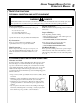
Grass Trimmer/Brush Cutter Operator's Manual MODELS SRM - 260 SRM - 260S Serial Number 03001001 - 03999999 WARNING DANGER Read rules for safe operation and instructions carefully. ECHO provides an Operator's Manual and a Safety Manual. Both must be read and understood for proper and safe operation. Failure to do so could result in serous injury.
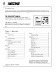
GRASS TRIMMER/BRUSH CUTTER OPERATOR'S MANUAL MANUAL SAFETY SYMBOLS AND IMPORTANT INFORMATION Throughout this manual and on the product itself, you will find safety alerts and helpful, information messages preceded by symbols or key words. The following is an explanation of those symbols and key words and what they mean to you. This symbol accompanied by the words WARNING and DANGER calls attention to an act or condition that can lead to serious personal injury to operator and bystanders.
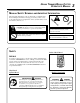
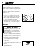
Shaft Decal P/N 89016844830 WARNING DANGER • This unit can be dangerous and cause serious injury if improperly • • • • • • • • used. To reduce injury risk to operator, helpers and bystanders, read and understand the Operator's and Safety manuals. Blindness can occur from objects that are thrown or ricocheted even with shield in place. Operators, helpers and bystanders must wear ANSI Z87.1 approved eye protection. Always wear hearing protection when operating unit.
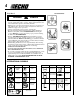
GRASS TRIMMER/BRUSH CUTTER OPERATOR'S MANUAL SAFETY INSTRUCTIONS PERSONAL CONDITION AND SAFETY EQUIPMENT WARNING DANGER Trimmer/Brush Cutter users risk injury to themselves and others if the trimmer/brush cutter is used improperly and or safety precautions are not followed. Proper clothing and safety gear must be worn when operating a trimmer.
Repetitive Stress Injuries It is believed that overusing the muscles and tendons of the fingers, hands, arms and shoulders may cause soreness, swelling, numbness, weakness and extreme pain in those areas. Certain repetitive hand activities may put you at a high risk for developing a Repetitive Stress Injury (RSI). An extreme RSI condition is Carpal Tunnel Syndrome (CTS), which could occur when your wrist swells and squeezes a vital nerve that runs through the area.
GRASS TRIMMER/BRUSH CUTTER OPERATOR'S MANUAL SAFE OPERATION WARNING DANGER Do not operate this product indoors or in inadequately ventilated areas. Engine exhaust contains poisonous emissions and can cause serious injury or death. • Provide all operators of this equipment with the Operator's Manual and instructions for safe operation.
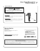
DESCRIPTION The ECHO product you purchased has been factory pre-assembled for your convenience. Due to packaging restrictions, shield installation and other assembly may be necessary. After opening the carton, check for damage. Immediately notify your retailer or ECHO Dealer of damaged or missing parts. Use the contents list to check for missing parts.
GRASS TRIMMER/BRUSH CUTTER OPERATOR'S MANUAL 1. 2. 3. 4. 5. 6. 7. 8. 9. 10. 11. 12. 13. 14. 15. 16. 17. 18. 19. 20. 21. 9 OPERATOR'S MANUAL - Included in plastic bag (co-pack). Read before operation and keep in a safe place for future reference, i.e., operation, maintenance, storage and specifications. SAFETY MANUAL - Included in plastic bag (co-pack). Read before operation and keep in a safe place for future reference to learn proper, safe operating techniques.
ASSEMBLY SPECIFICATIONS MOD E L S R M-260 S R M-260S 1795 mm (70.7 i n.) Length w/o cutter head Wi dth 250 mm (9.84 i n.) Hei ght 250 mm (9.84 i n.) Wei ght (dry) w/C utter Head E ngi ne Type 5.39 kg (11.9 lb.) 5.2 kg (11.5 lb.) A i r cooled, two-stroke, si ngle cyli nder gasoli ne engi ne B ore 34.0 mm (1.34 i n.) S troke 28.0 mm (1.10 i n.) 25.4 cc (1.55 cu. i n.
GRASS TRIMMER/BRUSH CUTTER OPERATOR'S MANUAL PLASTIC SHIELD INSTALLATION (for Nylon Line Operation) Tools Required: Screwdriver. Parts Required: Plastic Shield, Shield Plate, three (3) 5mm x 15mm screws. NOTE The plastic shield is for use with the Nylon Line Head only. Install Metal Shield when using plastic or metal blades. 1. Remove plastic threaded shaft sleeve and adapter plate (C) from PTO shaft (A). 2. Place the shield on the bottom of the bearing housing flange. 3.
OPERATION WITH BLADES Preparing the Trimmer/Brush Cutter for Blade Use WARNING DANGER Blade use DEMANDS specific Brush Cutter configuration. Operation without specified shield and harness can result in serious personal injury. Plastic and Nylon Blades Require "Blade Conversion Kit," P/N 99944200415 (TRI-CUT [A] and shoulder harness [B]). A B or U-Handle/Blade Conversion Kit P/N 99944200561 (metal blade [C] and shoulder harness [B]).
GRASS TRIMMER/BRUSH CUTTER OPERATOR'S MANUAL 8 Tooth Weed/Grass Blade (P/N 69600120331) is designed for grass, garden debris, and thick weeds. DO NOT use this blade for brush or heavy woody growth, 19 mm (3/4 in.) diameter or larger. Brush/Clearing Blade (P/N 69500120330) is designed for cutting brush and woody growth up to 76 mm (3 in.) diameter.
2. Remove front handle. a. Remove four (4) screws and nuts and handle support from handle. b. Remove handle. 3. Install clamp and front handle. 4. Install gear housing with metal shield and blade. (See Metal Shield and Blade Installation Instructions below.) 5. Balance unit. a. Put on harness and attach unit to harness. b. Slide harness clamp (C) up or down until unit balances with cutting attachment approximately 2 - 3 in. from the ground. c. Tighten harness clamp screw.
GRASS TRIMMER/BRUSH CUTTER OPERATOR'S MANUAL 3. Install upper plate (D) on splined shaft. Blade installation requires use of Upper Plate (D) with 20mm pilot. Upper plate with 37mm pilot of the SRM-260/260S should be retained for use with nylon line head. 4. Place Blade (E) over upper plate pilot, install the Lower Plate (F) and 10mm LH nut (G). Tri-Cut Blade (H) is installed with Glide Cup (J). 5.
10. Install upper U-Handle and bracket on lower bracket and secure with one (1) 8mm x 55mm bolt (K) and large circular washer. K 11. Install power head and align gear box, power head and U-Handles. Tighten all screws. 12. Route throttle linkage and ignition lead assembly behind U-Handle bracket, and clip to drive shaft as shown. 13. Place throttle linkage in slot in bracket. One nut on each side of bracket. Finger tighten both nuts (D). A 14. Attach inner cable to swivel (C).
GRASS TRIMMER/BRUSH CUTTER OPERATOR'S MANUAL 17 PRE - OPERATION FUEL Fuel Requirements Gasoline - Use 89 Octane [R +2 M] (mid grade or higher) gasoline known to be good quality. Gasoline may contain up to 15% MTBE (methyl tertiary-butyl ether). Gasohol containing methyl (wood) alcohol is NOT approved. Two Stroke Oil - A two-stroke engine oil meeting ISO-L-EGD (ISO/CD 13738) and J.A.S.O. FC Standards, must be used. Echo brand Premium 50:1 oil meets these standards.
OPERATION STARTING COLD ENGINE WARNING DANGER The cutting attachment should not rotate at idle. If attachment rotates, readjust carburetor according to "Carburetor Adjustment" instructions in this manual or see your ECHO Dealer, otherwise serious personal injury may result. 1. Stop Switch Move stop switch button (A) forward away from the STOP position. 2. Close Choke Move choke lever (B) to Cold Start Position. A B 3.
GRASS TRIMMER/BRUSH CUTTER OPERATOR'S MANUAL STARTING WARM ENGINE The starting procedure is the same as Cold Start except DO NOT close the choke. WARNING DANGER When engine starts, the cutting attachment may rotate even with the throttle trigger in idle (released) position. A 1. Stop Switch Move stop switch button (A) forward away from the STOP position. 2. Primer Pump primer bulb (C) until fuel is visible in the "Clear" fuel return line. 3.
MAINTENANCE Your ECHO unit is designed to provide many hours of trouble-free service. Regular scheduled maintenance will help your unit achieve that goal. If you are unsure or are not equipped with the necessary tools, you may want to take your unit to an ECHO Service Dealer for maintenance. To help you decide whether you want to DO-IT-YOURSELF or have the ECHO Dealer do it, each maintenance task has been graded. If a task is not listed, see your ECHO Dealer for repairs.
GRASS TRIMMER/BRUSH CUTTER OPERATOR'S MANUAL AIR FILTER Level 1. Tools required: Cleaning brush, 25 or 50 mm (1 or 2 in.) medium bristle paint brush. Parts required: 90030 REPOWERTM AIR & FUEL FILTER KIT. 1. Close choke (Cold Start Position). This prevents dirt from entering the carburetor throat when the air filter is removed. Brush accumulated dirt from the air cleaner area. 2. Remove the air cleaner cover. Clean and inspect the element for damage. If element is fuel soaked and very dirty, replace.
SPARK PLUG Level 2. Tools Required: T-Wrench (combination socket wrench and screw driver supplied with unit), Feeler gauge, preferably a wire gauge, Soft Metal Brush. Parts Required: REPOWERTM TUNE-UP KIT 90065 1. Remove spark plug and check for fouling, worn and rounded center electrode. 2. Clean the plug or replace with a new one. DO NOT sand blast to clean. Remaining sand will damage engine. 3. Adjust spark plug gap by bending outer electrode. 4.
GRASS TRIMMER/BRUSH CUTTER OPERATOR'S MANUAL 1. Remove spark plug lead. 2. Remove two (2) muffler cover screws and muffler cover (A). 3. Remove screw and arm rest (B). 4. Remove engine cover (C). C B A IMPORTANT DO NOT use a metal scraper to remove dirt from the cylinder fins. 5. Use brush to remove dirt from the cylinder fins. 6. Remove grass and leaves from the grid between the recoil starter and fuel tank. EXHAUST SYSTEM Spark Arrestor Screen Level 2.
1. Remove engine cover (A). See “Cleaning Cooling System” pages 22 & 23 for step by step instructions. 2. Place piston at Top Dead Center (TDC) to prevent carbon/dirt from entering cylinder. 3. Remove spark arrestor screen cover (B), screen holder (C), gasket (D), and screen (E), from muffler body. 4. Clean carbon deposits from screen and muffler components. 5. Replace screen if it is cracked, plugged, or has holes burned through. 6. Assemble components in reverse order.
GRASS TRIMMER/BRUSH CUTTER OPERATOR'S MANUAL 1. Check idle speed and reset if necessary. If a tachometer is available, idle speed screw (A) should be set to the specifications found on page 10 "Specifications" of this manual. Turn idle screw (A) clockwise to increase idle speed; counter clockwise to decrease idle speed. A WARNING DANGER When carburetor adjustment is completed, the cutting attachment should not turn at idle, otherwise serious personal injury may result. LUBRICATION Level 1.
NYLON LINE REPLACEMENT Level 1. Tools Required: Head locking tool (if head is to be removed) Parts Required: ECHO 0.095" Nylon Trimmer Line 12 m (40 feet) long. 1. Hold drum (A) and turn spool (B) CW (clockwise) until it stops. Pull spool from drum. DO NOT push in on spool when turning. 2. Use one piece of new nylon line (C) 12 m (40 ft.) long and thread through the molded loop (D) on the spool. Pull line tight and adjust so one end is 15 cm (6 in.) longer than the other. 3.
GRASS TRIMMER/BRUSH CUTTER OPERATOR'S MANUAL SHARPENING METAL BLADES Three styles of metal blades are approved for use on the ECHO Brush Cutter. The 8-tooth blade can be sharpened during normal maintenance. The clearing blade and 80 tooth blade require professional service. Before sharpening, CLOSELY inspect blade for cracks (look at the bottom of each tooth and the center mounting hole closely), missing teeth and bending. If ANY of these problems are discovered, replace the blade.
TROUBLESHOOTING EN GIN E PR OB LEM TR OU B LESH OOTIN G C H AR T Problem C h eck Status Fuel at carburetor No fuel at carburetor No fuel at cyli nder Engi ne cranks starts hard/ doesn't start Engi ne runs, but di es or does not accelerate properly C au se R emedy Fuel strai ner clogged Fuel li ne clogged C arburetor C lean or replace C lean or replace See your Echo dealer C arburetor See your Echo dealer Fuel at cyli nder Muffler wet wi th fuel Fuel Mi xture too ri ch Open choke C lean/repl
GRASS TRIMMER/BRUSH CUTTER OPERATOR'S MANUAL 29 STORAGE Long Term Storage (over 30 days) DANGER WARNING During operation the muffler or catalytic muffler and surrounding cover become hot. Always keep exhaust area clear of flammable debris during transportation or when storing, otherwise serious property damage or personal injury may result. Do not store your unit for a prolonged period of time (30 days or longer) without performing protective storage maintenance which includes the following: 1.
NOTES
GRASS TRIMMER/BRUSH CUTTER OPERATOR'S MANUAL NOTES 31
SERVICING INFORMATION PARTS Genuine ECHO Parts and ECHO REPOWER™ Parts and Assemblies for your ECHO products are available only from an Authorized ECHO Dealer. When you do need to buy parts, always have the Model Number and Serial Number of the unit with you. You can find these numbers on the engine housing. For future reference, write them in the space provided below. Model No. _____________ SN. ____________ SERVICE DEALER? CALL 1-800-432-ECHO OR www.echo-usa.
SUPPLEMENT TO OPERATOR'S MANUAL * Some Echo units may be factory pre-assembled. The nylon line head, plastic debris shield, and mounting hardware shown in the contents list are pre-assembled to the unit. No assembly tools are needed. The front handle may need to be re-positioned for comfortable operation. GT CONTENT LIST * _ - Rapid LoaderTM 2-line Head * _ - Shield Assembly * _ - Line Head Mount Hardware * _ - 1, 3/8-24 Locknut * _ - 1, Small Washer * _ - 1, Large Washer * _ - 12, 8 in. x .